 Loading...
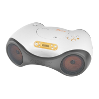
Do you have a question about the Sony ZS-X3CP and is the answer not in the manual?
| digital filter | 8X Oversampling |
|---|---|
| digital to analog conversion | 1 Bit |
| cd frequency response | 20-20000Hz, +1, -2dB |
| tuner frequency range AM | 530-1710kHz |
|---|---|
| tuner frequency range FM | 87.6-108MHz |
| antenna system AM | Built-in Ferrite Bar Antenna |
| antenna system FM | Telescopic Antenna |
| speakers | 4" (10cm) x 2 |
|---|---|
| outputs | Headphone (stereo mini jack) |
| power requirements batteries | “D” x 6 Batteries (optional) |
|---|---|
| power requirements AC | AC 120V, 60Hz |
| inputs | DC In |
| dimensions | 16 [7]⁄8" x 6 [3]⁄4" x 11 [1]⁄4" (430 x 172 x 287.5mm) |
|---|---|
| weight | 8 lbs 8 [2]⁄3 oz (3.8kg) w/batteries |
Describes audio output power and distortion.
Details on CD player and radio sections.
Covers speaker, outputs, power requirements, and dimensions.
Notes on handling components and circuit boards during repair.
Procedure to check for AC leakage from exposed metal parts.
Information on playable CD formats and MP3 files.
Precautions for handling the optical pick-up block to prevent damage.
Procedure for checking laser diode emission and focus search.
Instructions for playing audio CDs and MP3 files.
Instructions for tuning and listening to radio stations.
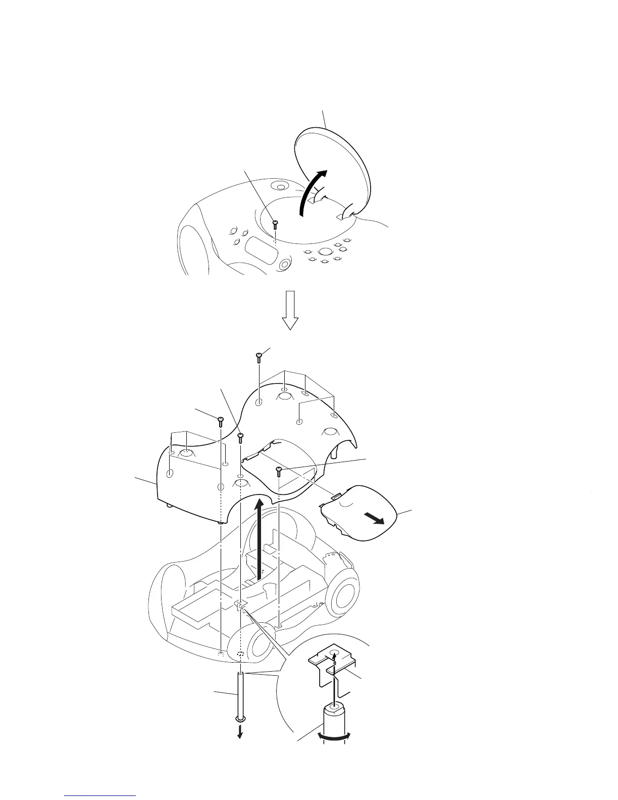
Visual guide to the sequence of disassembly steps.
Steps to remove the lower cabinet and telescopic antenna.
Steps for removing the tuner and control boards.
Steps to remove the CDMP3 board.
Steps to remove the optical pick-up section.
Steps to remove the sled motor assembly.
Steps to remove the optical pick-up unit.
Steps to remove the front cabinet section.
Steps to remove the left and right speakers.
Steps to remove the CD lid.
Procedures for AM/MW/LW and FM tuner adjustments.
Diagrams showing the location of adjustment points on tuner boards.
Procedure to enter CD test mode for diagnostics.
Procedures for checking focus bias and traverse operations.
Block diagram illustrating the CD section's signal flow.
Block diagram illustrating the tuner section's signal flow.
Block diagram illustrating the main control and power sections.
Notes on interpreting schematics and printed wiring boards.
Diagrams indicating the physical location of circuit boards.
Oscilloscope waveform examples for various ICs in the CD section.
Component and conductor side views of CD section PCBs.
Detailed schematic for the CD section (first half).
Detailed schematic for the CD section (second half).
Printed wiring board layout for the tuner section (US/Canadian models).
Schematic diagram for the tuner section (US/Canadian models).
Printed wiring board layout for tuner section (non-US/Canadian models).
Schematic diagram for tuner section (non-US/Canadian models).
Printed wiring board layouts for control, LCD, button, and enter boards.
Schematic diagram for the control section, including connections to other boards.
Printed wiring board layouts for audio, jack, and battery boards.
Schematic diagram for the audio/power section, including jack and battery boards.
Block diagrams for key ICs in the CDMP3 and Tuner sections.
Detailed pin function descriptions for IC703 (MP3 Decoder).
Exploded view and parts list for the lower cabinet assembly.
Exploded view and parts list for the front cabinet assembly.
Exploded view and parts list for the upper cabinet assembly (part 1).
Exploded view and parts list for the upper cabinet assembly (part 2).
Exploded view and parts list for the upper cabinet assembly (part 3).
Exploded view and parts list for the main chassis.
Exploded view and parts list for the optical pick-up unit.
Detailed list of electrical components for the audio board.
Component lists for battery, button power, and CDMP3 boards.
Detailed component listings for the CDMP3 board.
Detailed component listings for the control board.
Component lists for control, enter, jack, and LCD boards.
Component lists for relay and tuner boards.
Detailed component listings for the tuner board.
Component lists for tuner, volume, miscellaneous items, and accessories.