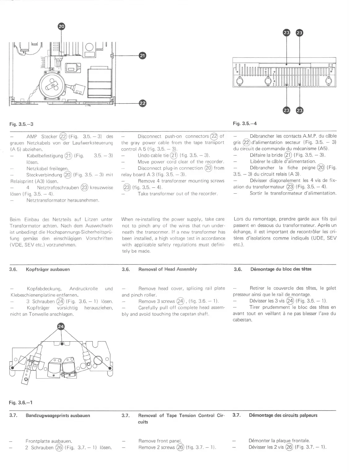
Fig. 3.5.-3
Fis.
3.5.-4
AMP Stecker
@
Ctn
3.5.
-
3) des
grauen
Netzkabels
von
der
Laufwerksteuerung
(A
5) abziehen.
Kabelbefestiguno
@
tfls.
3.5.
-
3)
lösen.
-
Netzkabel
freileqen.
-
Steckverbindung
@
lFn
3.5.
-
3) mir
Relaisprint
(43)
lösen.
-
4 Netztrafoschrauben@kreuzweise
lösen
(Fi9.3.5.
-
4).
Netztransformator herausnehmen.
Beim
Einbau des
Netzteils auf Litzen unter
Transformator achten. Nach
dem Auswechseln
ist
unbedingt
die Hochspannungs-Sicherheitsprü-
fung
gemäss
den einschlägigen
Vorschriften
(VDE.
SEV
etc.) vorzunehmen.
Disconnect
push-on
connectors
€D
of
the
gray power
cable
from the tape transport
control A 5
(iig.
3.5.
-
3).
Undo cable
rie
€)
ttis.
3.5.
-
3).
Move
power
cord clear
of the recorder.
Disconnect
plug-in
connection
@Q
from
relay board A 3
(fiS
3.5.
*
3).
Remove
4 transformer mounLing
screws
@
tr,n
3.b.
-
4).
Take transformer out
of the recorder.
Ddbrancher
les
contacts
A-M.P. du cäble
gris
@d'alimentation
secteur
(Fig.
3.5.
-
3)
du circuit de commande
du mdcanisme
(A5).
D6faire
la bride
@
(Fig.
3.5.
-
3).
Lib6rer le cäble d'alimentation.
Döbrancher
la fiche
peigne@(fig.
3.5.
-
3) du circuit relais
(A
3).
-
Dövisser diagonalement
les
4 vis
de
fix-
ation du rransformareur
€9
tf
ig 3.5.
-
4).
Sortir le transformateur d'alimentation.
When re-installing
the
power
supply, take care
not to
pinch
any of the wires that
run
under-
neath the transormer.
lf
a
new transformer has
been
installed, a high voltage test in accordance
with applicable
safety regulations
must
defini-
tely be made.
Lors du remontage,
prendre
garde
aux
fils
qui
passent
en dessous du transformateur.
Aprös un
6change,
il est important de recontröler
les cri-
töres d'isolations comme indiquds
(UDE,
SEV
etc.
).
Kopfabdeckung, Andruckrolle
Klebeschlenenplati
ne entfernen.
3 Schrauben
@
trin.
3.6.
-
1) lösen.
Kopfträger vorsichtig herausziehen,
nicht
an Tonwelle anschlagen.
3.6.
Kopfträgerausbauen
Fis. 3.6.-1
und
3.6. Removal
of
Head Assembly
Remove
head cover, splicing
rail
plate
and
pinch
roller.
-
Remove
3 screws
@
,trtn.3.6.
-
1).
Carefully
pull
o{f complete
head
assem-
bly and avoid
touching the capstan
shaft.
3,6.
D6montage
du bloc
des tetes
Retirer le couvercle des t6tes, le
galet
presseur
ainsi
que
le rail de montage.
-
Dövisser les
3
vis
Ql
lrig.
3.6.
-
1).
Tirer
prudemment
le bloc des tCtes en
avant
tout en
veillant
ä ne
pas
blesser l'axe du
cabestan.
2 Schrauben
@
trig.
g.7.
-
1) lösen.
3.7.
3.7.
Bandzugwaageprintsausbauen
Frontplatte
ausbauen.
Removal
of Tape Tension
Control
Cir-
3.7.
cuits
D6montage
des circuits
palpeurs
Ddmonter
la
plaque
frontale.
D6visser les 2 vis
Q0
trig.
3J
.
-
1il.
Remove front
panel.
Remove 2 screws
@
lfin.
3.1.
-
1'l
 Loading...