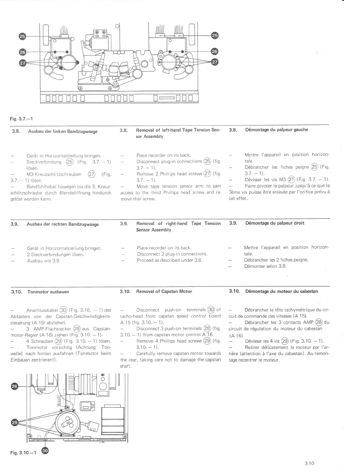
Fig. 3.7.-1
3.8.
Ausbau
der linken
Bandzugwaage
-
GeräL
in Hor,zonLalsLellung
bringen.
-
Sreckverbindung
@
trig
3.7.
-
1)
lösen.
-
M3 Kreuzschlirzschrauben
@
(Fi9
3.7.
-
1)
lösen.
Bandfühlhebel bewegen bis die 3. Kreuz-
schlitzschraube durch Blendeöffnung hindurch
gelöst
werden
kann.
Removal
of
left-hand Tape
Tension Sen-
sor
Assembly
Place
recorder on
its back.
Disconnect
plug-in
connections
@
(fio.
3.1
.
-
1\.
Remove 2
Phillips
head screws
@
ttrn
3.7.
-
1).
-
Move
lape
tension sensor
arm
ro
gain
access
to the
third Phillips
head screw
and
re-
move
that
screw.
3.8.
D6montage
du
palpeur gauche
Mettre l'appareil
en
position
horizon-
tale.
Ddbrancher
les
fiches
peigne
(2-s)
(rio.
3.t ,
-
1]|.
Ddvisser
les vis M3
@
trig.
3.1
.
-
1).
Faire
pivoter
le
palpeur
jusqu'ä
ce
que
la
3öme vis
puisse
ötre
enlev6e
par
l'orifice
pr6vu
ä
cet effet.
3.8.
3.9.
3.9. Ausbau
der rechten
Bandzugwaage
Gerät
in Horizontalstellung bringen.
2 Steckverbindungen
löserr.
Ausbau wie 3.8.
3.9.
Removal of
right-hand Tape Tension
Sensor
Assembly
Place
recorder
on
its back.
Disconnect 2
plug-in
connections
Proceed as described under
3.8.
D6montage du
palpeur
droit
Mettre
l'apparail en
position
horizon
tale.
Döbrancher
les 2
fiches
peigne.
Dömonter
selon
3.8.
3.10.
Tonmotorausbauen
-
Anschlusskabel
@
(Fig.3.10.
-
1)
des
Abtasters
von
der
Capstan-Geschwindigkeits-
steuerung
(A
15) abziehen.
3 AMP-Flachstect<er
@
aus Capstan-
motor-Reqler
(A
16) ziehen
(Fi9.3.10.
-
1).
4 Schrauben
@
trig.
3.10.
-
1) lösen.
Tonmotor
vorsichtig
(Achtung:
Ton-
welle) nach
hinten ausfahren
(Tonmotor
beim
Einbauen zentrierenl ).
3.10. Removal
of
Capstan
Motor
Disconnect
push-on
terminals
@
of
tacho-head
from capstan speed
control board
A
15
(fis.
3.10.
-
1).
-
Disconnect 3
push-on
terminals
@
tt'n.
3.1
0.
-
1
)
from capstan motor control
A
1
6.
Remove
4
Phillips
head screws
@
lt'n.
3.10.
-
1).
Caref ully remove
capstan motor
towards
the rear, taking care
not to
damage
the
capstan
shaft.
3.10.
D6montage
du moteur du cabestan
Döbrancher
la täte tachymdtrique
du cir-
cuit de commande des
vitesses
(A
15).
D6brancher
les 3 contacts
nMP
@
du
circuit de rögulation du
moteur du cabestan
(A
16)
D6visser
les 4 vis
Q9
tf
ig 3.10.
-
1).
Retirer
ddlicatement
le moteur
par
l'ar-
riöre
(attention
ä l'axe du
cabestan). Au
remon-
tage recentrer le moteur.
3.1
0
 Loading...