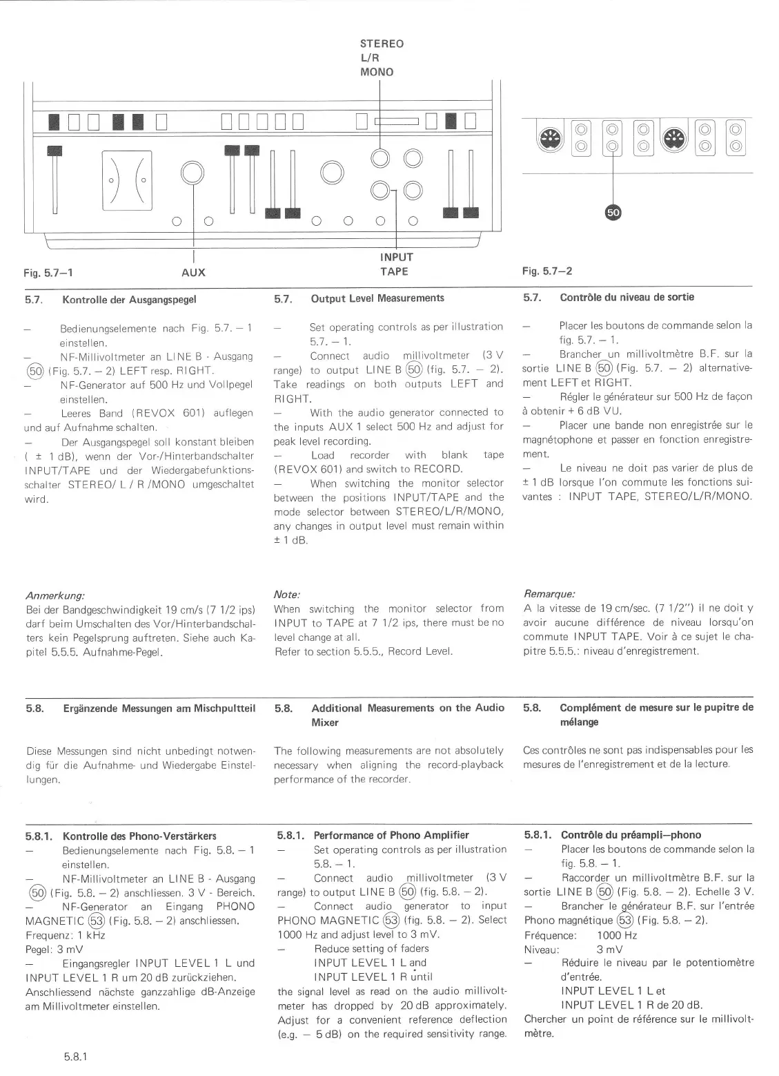
Fig. 5.7-1
AUX
STEREO
L/R
MONO
TAPE
Fig.5.7-2
TT ITTN!
T
T
a
'I|ltll
o
3
cl"lllllL.
o o
o ilil
o llll
ott
5.7. Kontrolle der
Ausgangspegel
-
Bedienungselemente
nach Fig. 5.7.
-
1
ei nstel
len.
-
NF-Millivoltmeter
an LINE
B
-
Ausgang
@
tFn
5.1
.
-
2\ LEFT
resp. R
IGHT.
-
NF-Generator auf 500
Hz und
Vollpegel
einstellen.
Leeres Band
(REVOX
601)
auflegen
und auf Aufnahme
schalten.
Der
Ausgangspegel soll
konstant
bleiben
(
t
1 dB), wenn der
Vor-/Hinterbandschalter
INPUT/TAPE und
der Wiedergabef
unktions-
schalter STEREO/ L/
R
/MONO
umgeschaltet
wird.
Anmerkung:
Bei der Bandgeschwindigkeit 19
cm/s
0
l12ipsl
darf
beim Umschalten
des Vor/Hinterbandschal-
ters kein Pegelsprung
auftreten. Siehe auch Ka-
pi
Lel 5.5.5. Aufnahme-Pegel.
5.7. Output
Level
Measurements
-
Set operatinq
controls as
per
illustration
5.1 .-1.
Connect
audio millivoltmeter
(3
V
range) to output
Ll
NE a
@
ttig.
5.1
.
-
2).
Take readings
on both
outputs
LEFT and
RIGHT.
With the
audio
generator
connected
to
the inputs AUX
1 select 500
Hz and adjust
for
peak
level recording.
Load
recorder with blank
tape
(REVOX
601)and
switch to
RECORD.
-
When
switching
the monitor
selector
between
the
positions
INPUT/TAPE
and the
mode selector between
STEREO/L/R/MONO,
any changes in output
level must remain
within
11d8.
Note:
When switching
the monitor
selector
from
INPUT to TAPE
at I 1/2
ips, there must
be no
level change at all.
Refer to section 5.5.5.,
Record Level.
5.7. Contröle
du
niveau de sortie
Placer
les boutons de commande
selon
Ia
fig.
5.7.
-
1.
Brancher un millivoltmötre
B.F. sur
la
sortie LINE a
@
lrig.
5.1
.
-
2) alternative-
ment LEFT et
RIGHT.
-
R6gler
le
gdnörateur
sur 500
Hz
de
faqon
ä obtenir
+
6 dB
VU.
Placer une
bande non enregistr6e
sur le
magndtophone
et
passer
en fonction enregistre-
ment.
Le
niveau ne doit
pas
varier de
plus
de
t
1
dB
lorsque l'on commute
les
fonctions
sui-
vantes : INPUT
TAPE, STEREO/L/R/IVIONO.
Remarque:
A la vitesse de 19 cm/sec.
l1
1/2"1
il ne doit
y
avoir
aucune
difförence de
niveau lorsqu'on
commute INPUT TAPE. Voir ä ce sujet
le cha-
pitre
5.5.5.:
niveau d'enregistrement.
5.8. Ergänzende Messungen am Mischpultteil
Diese Messungen sind nicht unbedingt
notwen-
dig
für
die Aufnahme- und Wiedergabe
Einstel-
I
u ngen.
Additional
Measurements on
the Audio
Mixer
The following
measurements
are not absolutely
necessary when aligning
the record-playback
performance
of the
recorder.
5.8. Compl6ment
de mesure
sur le
pupitre
de
m6lange
Ces contröles
ne sont
pas
indispensables
pour
les
mesures de
l'enregistrement et de
la lecture.
5.8.
5.8.1. Kontrolle des
Phono-Verstärkers
Bedienungselemente
nach Fig. 5.8.
-
1
ei nstel
len.
NF-Millivoltmeter an LINE
B
-
Ausgahg
@
tfin.
5.8.
-
2) anschliessen.
3 V
-
Bereich.
NF-Generator
an Eingang
PHONO
MAGNETIC
@
lrig.
5.8.
-
2) anschliessen.
Frequenz:
1 kHz
Pegel:
3
mV
Eingangsregler
INPUT
LEVEL
1
L und
INPUT LEVEL
'l
R um 20 dB zurückziehen.
Anschliessend nächste
ganzzahlige
dB-Anzeige
am Millivoltmeter einstellen.
5.8.1. Performance of
Phono Amplifier
Set operating
controls as
per
illustration
5.8.
-
1.
Connect
audio millivoltmeter
(3
V
range) to output
Ll N E a
@
ltig.
5.8.
-
2) .
Connect
audio
generator
to
inPut
PHONO MAGNETIC
@
tt'n.
5.8.
-
2).
Select
1000 Hz and
adjust
level to
3
mV.
Reduce
setting of faders
INPUTLEVELl
Land
INPUTLEVELl
Rüntil
the
signal
level as
read on the audio
millivolt-
meter has
dropped by
20 dB approximately.
Adjust for a convenient
reference deflection
(e.g.
-
5dB)
on
the required
sensitivity
range.
5.8,1. Contröle du
pr6ampli-phono
Placer
les
boutons de
commande selon la
fis. 5.8.
-
1.
Raccorder
un millivoltmötre
B.F. sur la
sortie
Ll
NE
a
@
trig.
5.8.
-
2\. Echelle 3
V.
Brancher le gdndrateur B.F. sur
l'entrde
Phono
magndtique
@)
t
f
io.
5.8.
-
21.
Frdquence: 1000
Hz
Niveau: 3
mV
Rdduire
le niveau
par
le
potentiomÖtre
d'entrde.
INPUT
LEVEL
1 Let
INPUT
LEVEL 1 R de
20 dB.
Chercher un
point
de rdfdrence sur
le millivolt-
mötre.
5.8.1
 Loading...