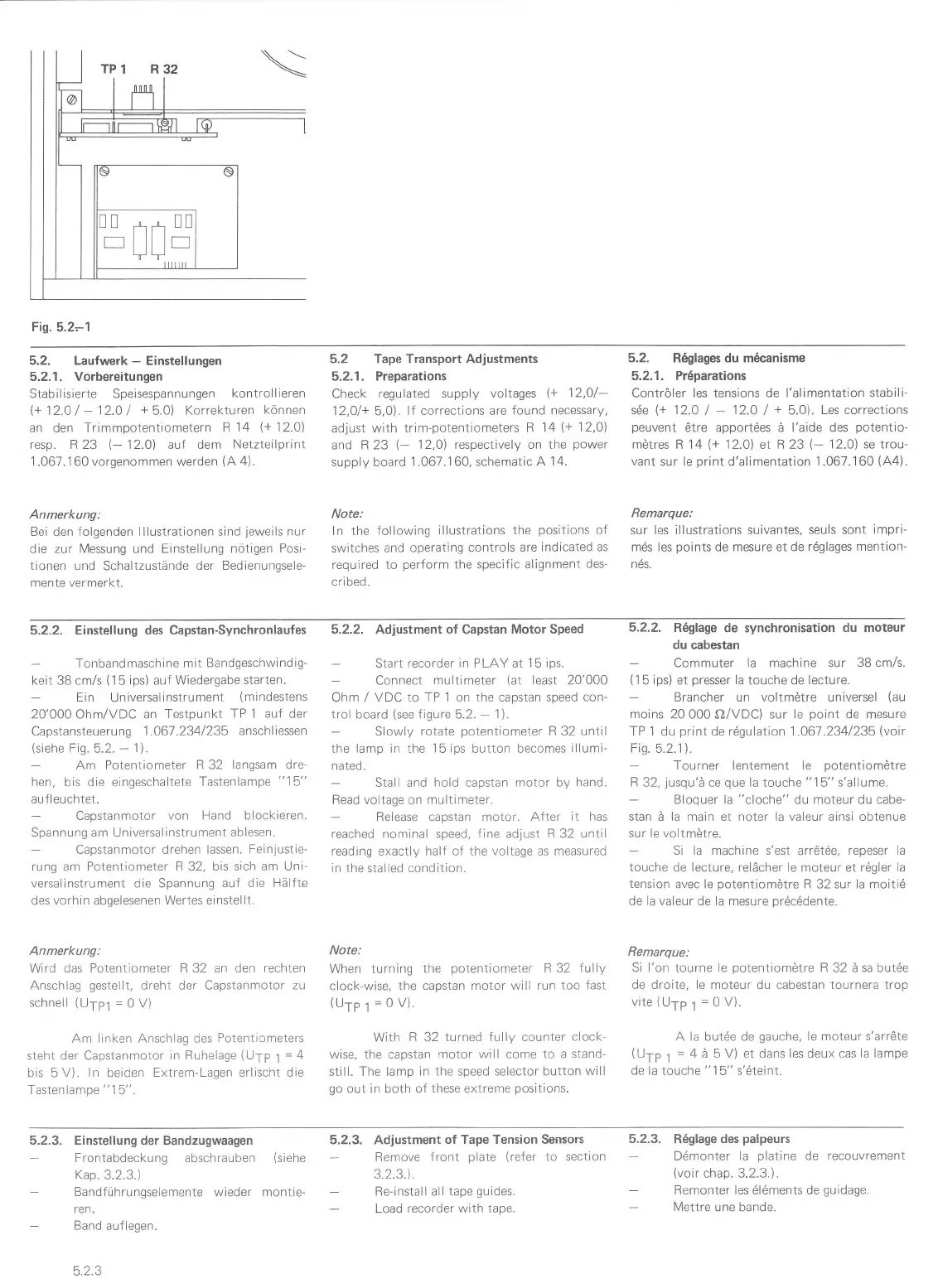
Fig.
5.2-1
5.2. Laufwerk
-
Einstellungen
5.2.1. Vorbereitungen
Stabilisierte Speisespannungen
kontrollieren
\+
12.O
/
-
12.0
I
+
5.0)
Korrekturen
können
an den
Trimmpotentiometern R
14
(+
12.O1
resp. R 23
(-
12.0) aut dem
Netzteilprint
1
.067. 1 60 vorgenom men werden
(A
4).
Anmerkung:
Bei den folgenden
lllustrationen sind
jeweils
nur
die zur
Messung
und
Einstellung nötigen
Posi-
tionen
und Schaltzustände
der Bedienungsele-
mente vermerkt-
5.2 Tape Transport Adjustments
5.2.1.
Preparations
Check regulated
supply voltages
\+
12,0/-
12,01+
5,O).
If corrections are
found necessary,
adjust with
trim-potentiometers
R 14
(+
12,01
and R 23
(-
12,OJ respectively on
the
power
supply board
1
.067.160,
schematic
A 14.
Note:
ln the following
illustrations
the
positions
of
switches and
operatinq
controls are indicated
as
required to
perform
the specific
alignment
des-
cri bed.
5.2.
R6glages du m6canisme
5.2.1. Pr6parations
Contröler les tensions de l'alimentation stabili-
sde
(+
12.0
/
-
12.0
/
+
5.0).
Les corrections
peuvent
6tre apport6es ä l'aide des
potentio-
mötres
R 14
(+
12.01 et R 23
F
12.O) se trou-
vant
sur le
print
d'alimentation
1.067.160
(A4).
Remarque:
sur les illustrations suivantes,
seuls sont
impri-
mds les
points
de mesure et de r6glages
mention-
nds.
5.2.2. Einstellung des Capstan-Synchronlaufes
Tonbandmaschine mit
Bandgeschwindig-
keit 38 cm/s
(15
ips)
auf
Wiedergabe
starten.
Ein
Universalinstrument
(mindestens
20'000 Ohm/VDC an
Testpunkt
TP 1 auf der
Capstansteuerung
1.067.2341235
anschliessen
(siehe
Fig.
5.2.
-
11.
Am Potentiometer
R 32
langsam dre-
hen,
bis die eingeschaltete
Tastenlampe
"15"
au fleuch tet.
Capstanmotor
von Hand blockieren.
Spannung am
Universal
instrument
ablesen.
Capstanmotor drehen
lassen. Feinjustie-
rung
am
Potentiometer R
32,
bis sich am Uni-
versalinstrument die Spannung auf
die Hälfte
des
vorhin
abgelesenen
Wertes einstellt.
Anmerkung:
Wird das
Potentiometer R 32 an den
rechten
Anschlag
gestellt,
dreht der Capstanmotor
zu
schnell
(UTp1
=0V)
Am
linken Anschlag des Potentiometers
steht der Capstanmotor
in Ruhelage
(U1p
1
=
4
bis 5 V).
ln
beiden Extrem-Lagen
erlischt die
Tastenlampe
"
1
5".
5.2.2. Adjustment
of
Capstan
Motor Speed
Start recorder
in
PLAY at
1
5
ips.
Connect
multimeter
(at
least 20'000
Ohm
/
VDC to TP 1 on the capstan speed
con-
trol
board
(see
figure 5.2.
-
1)
Slowly rotate
potenliometer
R
32
until
the lamp in the
15 ips
button becomes
illumi-
nated.
Stall and
hold
capstan motor
by hand.
Flead volLage
on
multimeter.
Release capstan motor.
After it has
reached nominal speed, fine adjust F 32 until
reading
exactly
half
of
the voltage
as measured
in the
stalled
condition.
Note:
When turning
the
potentiometer
R 32 fully
clock-wise, the
capstan motor will run
too fast
(uTP1=ov).
With
R
32
turned fully counter
clock-
wise, the capstan
motor
will
come to a stand-
still. The lamp
in the speed selector button
will
qo
out in both of
these
extreme
posiLions.
5.2.2.
R6glage
de synchronisation
du moteur
du
cabestan
Commuter la machine sur
38 cm/s.
(
1
5 ips) et
presser
la touche de lecture.
Brancher un voltmötre universel
{au
moins
20 000 O/VDC) sur le
point
de mesure
TP 1 du
print
de r6gulation 1.067.2341235
(voir
Fis.
5.2.1).
Tourner lentement
le
potentiomötre
R 32,
jusqu'ä
ce
que
la
touche
"15"
s'allume.
Bloquer la
"cloche"
du moteur du cabe-
stan ä la main et noter la valeur ainsi obtenue
sur le voltmötre.
Si la machine s'est
arrröt6e,
repeser la
touche
de
lecture,
relächer le moteur et rdgler
la
tension
avec le
potentiomötre
R 32 sur la moitid
de la valeur de la mesure
pr6cddente.
Remarque:
Si l'on tourne le
potentiomötre
R
32
ä sa butöe
de droite, le moteur du cabestan tournera trop
vite(U1pt
=0V).
A la but6e de
gauche,
le moteur s'arrÖte
(Ufp
t
=
4 ä 5 V) et dans lesdeux
cas la lampe
de
la
touche
"1
5" s'6teint.
5.2.3. Einstellungder
Bandzugwaagen
Frontabdeckung
abschrauben
(siehe
Kap.
3.2.3.)
Bandführungselemente
wieder montie-
ren.
Band
auflegen.
Adiustment
of Tape Tension Sensors
Remove lront
plate
(refer
to section
3.2.3.).
Re-instali all tape
guides.
Load
recorder with
tape.
5.2,3. R6glage
des
palpeurs
D6monter
la
platine
de recouvrement
(voir
chap.
3.2.3.).
Remonter les 616ments de
guidage.
Mettre une bande.
5.2.3.
5.2.3
 Loading...