10 Appendix User Manual
Note(4):The inverter enters the standby state when the input voltage ranges between 1,000V
and 1,100V. If the maximum DC voltage in the system can exceed 1000V, the MC4 connectors
included in the scope of delivery must not be used. In this case MC4 Evo2 connectors must
be used.
Note(5):The voltage difference between MPPTs should be less than 80 V. The voltage of the
configured string should be higher than the lower limit of the rated MPPT voltage.
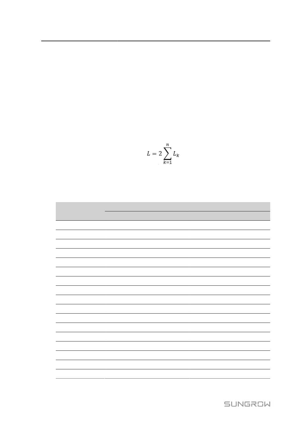
10.2 Wring Distance of DI Dry Contact
The wiring distance between DI dry contact terminals must meet the requirements in the table
below. The wiring distance L is the total length of all DI signal cables.
L
K
refers to the cable length in one direction between the DI dry contact terminal of the k
th
inverter and the corresponding terminal of the (k-1)
th
inverter.
table 10-1 Correspondence Between Inverter Quantity and Maximum Wiring Distance
Maximum Wiring Distance(unit:m)
Number of In
verter
16AWG / 1.31mm
2
17AWG / 1.026mm
2
1 13030 10552
2 6515 5276
3 4343 3517
4 3258 2638
5 2606 2110
6 2172 1759
7 1861 1507
8 1629 1319
9 1448 1172
10 1303 1055
11 1185 959
12 1086 879
13 1002 812
14 931 754
15 869 703
16 814 660
17 766 621
118
 Loading...