User Manual 5 Electrical Connection
Item Terminal Mark Note
COM1 / 2 / 3
RS485 communication, digital input/output DI/
DO.
B
Communica
tion terminal
COM4 For communication module connection.
C
AC wiring ter
minal
Used for AC output cable connection.
D
Standby
grounding ter
minal*
AC
Used for internal grounding.
E
External pro
tective
grounding ter
minal
use at least one of them to ground the inverter.
*If the PE cable is an independent single-core cable, it should be inserted into the cabinet
through the standby grounding terminal.
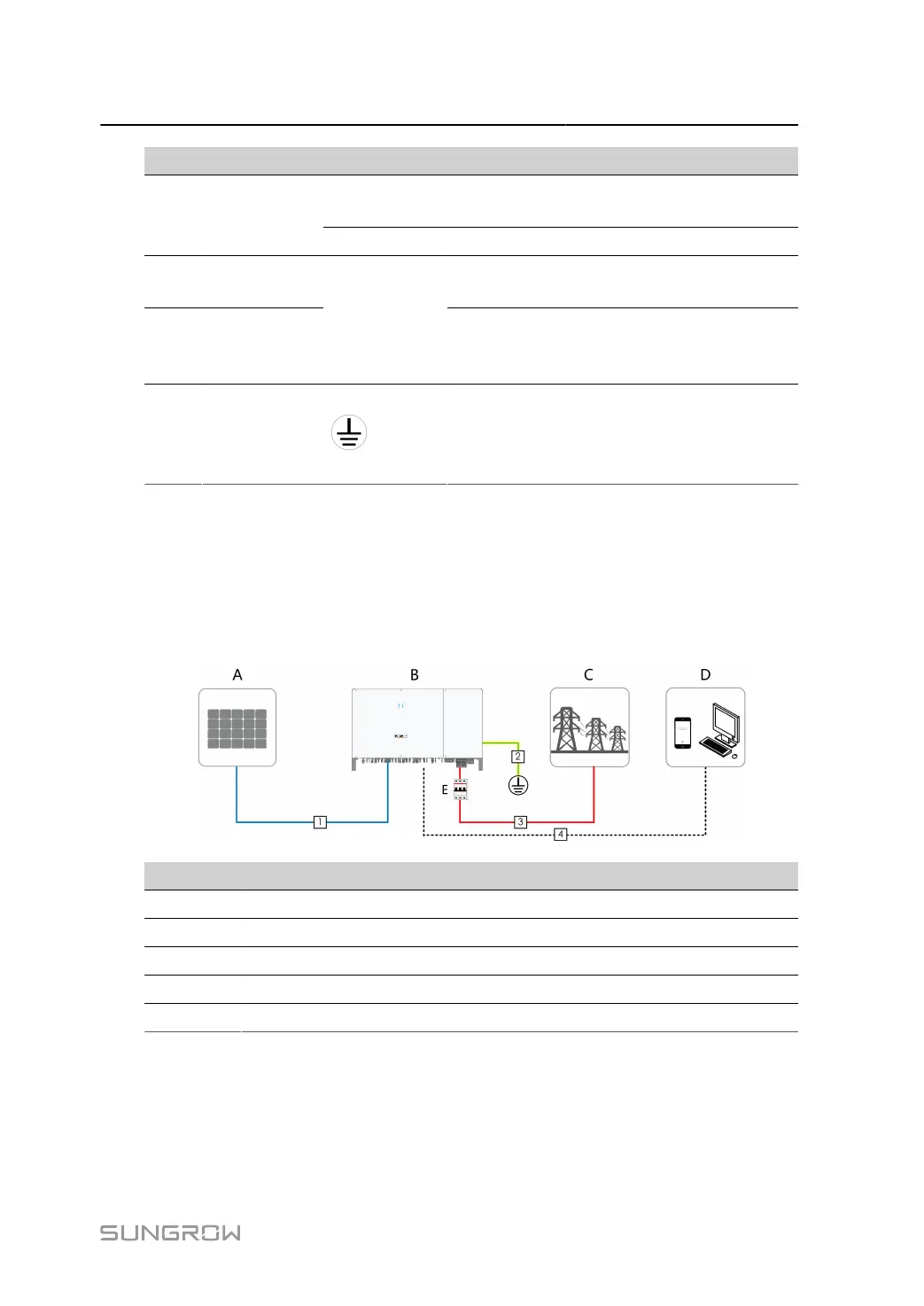
5.3 Electrical Connection Overview
The electrical connection should be realized as follows:
Item Designation
A PV string
B Inverter
C Grid
D Monitoring device
E AC circuit breaker
35
 Loading...