User Manual 2 Product Description
Appearance
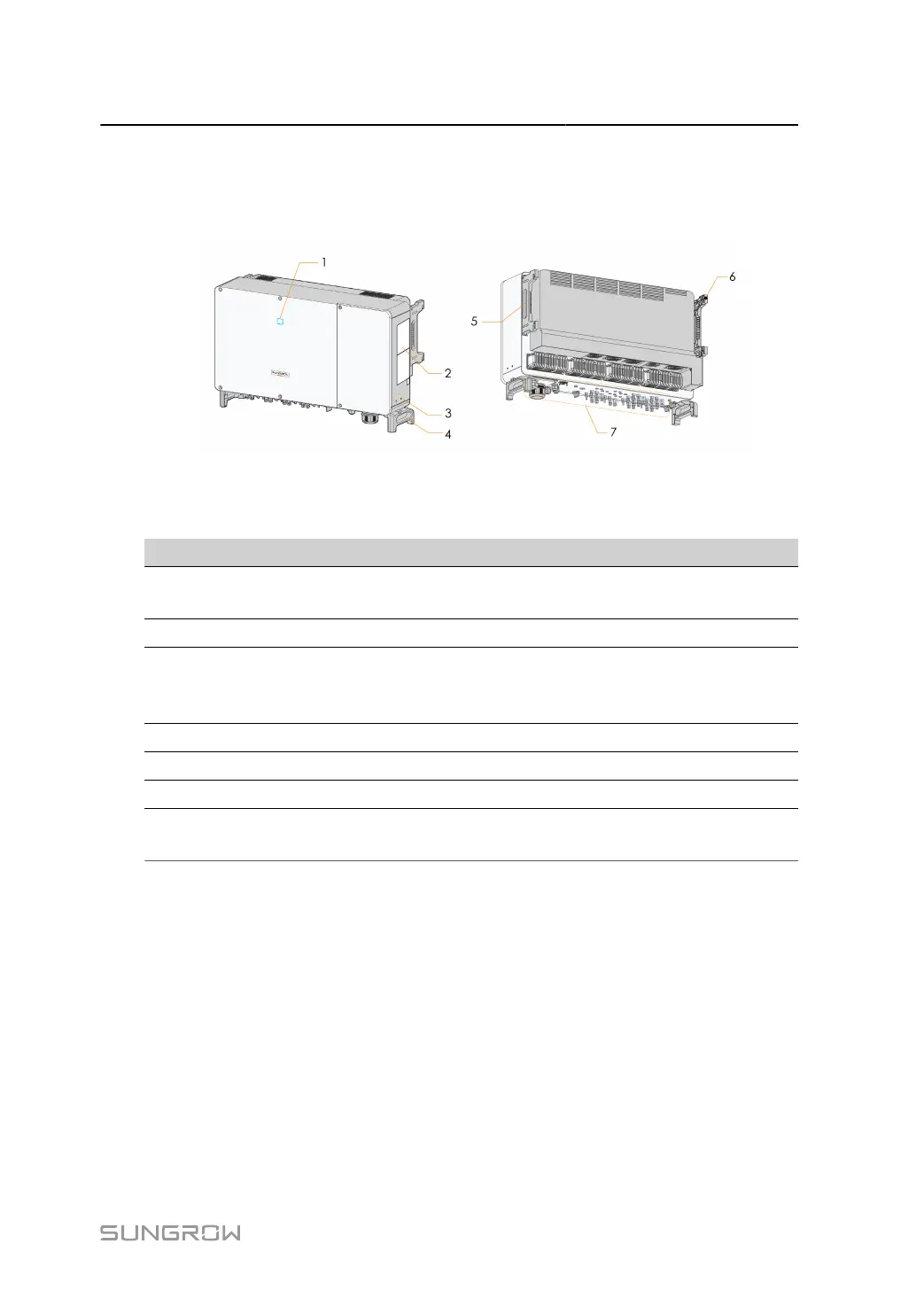
The following figure shows the appearance of the inverter. The image shown here is for refer
ence only. The actual product received may differ.
figure 2-2 Inverter Appearance
* The image shown here is for reference only. The actual product received may differ.
No. Name Description
1
LED indicator pan
el
HMI interface to indicate the present working state of the in
verter.
2 Labels Warning symbols, nameplate, and QR code.
3
External protective
grounding termi
nals
2, use at least one of them to ground the inverter.
4 Bottom handles 2, used to move the inverter.
5 Side handles 2, used to move the inverter.
6 Mounting lugs 4, used to hang the inverter onto the mounting-bracket.
7 Wiring area
DC switches, DC terminals, and communication terminals. For
details, refer to5.2 Terminal Description
Dimensions
The following figure shows the dimensions of the inverter.
9
 Loading...