5 Electrical Connection User Manual
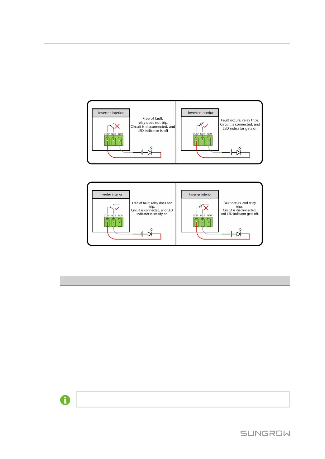
The relay is initially at the NC contact, and it will trip to another contact when a fault occurs.
When alarm occurs, signal status change will not be triggered.
Use LED indicators or other equipment to indicate whether the inverter is in the faulty state.
The following Figures show the typical applications of normally open contact and normally
closed contact:
figure 5-8 Normally open contact
figure 5-9 Normally closed contact
Devices connected to the relay should comply with related requirements:
AC-Side Requirements DC-Side Requirements
Max. voltage: 125Vac
Max. current: 5A
Max. voltage: 30Vdc
Max. current: 5A
DI terminal (emergency stop dry contact): the dry contact can be configured to be an emer
gency stop contact. Use either of the following methods for configuration.
Method
1:
When the DI + contact and DI
﹣
contact are shorted by external controlled switch
(The external switch can be configured as normally open contact or normally closed contact),
the inverter will immediately shutdown.
Method
2:
Passive Valid can be set. When Passive Valid is enabled on the iSolarCloud, the
inverters will operate normally when DI + contact and DI
﹣
contact are shorted by external con
trolled switch, and the inverters will emergently stop when DI + contact and DI
﹣
contact are
disconnected.
The dry contacts only support passive switch signal input.
66
 Loading...