9
3 Product Description
3.1 Inverter Appearance
3.1.1 Appearance
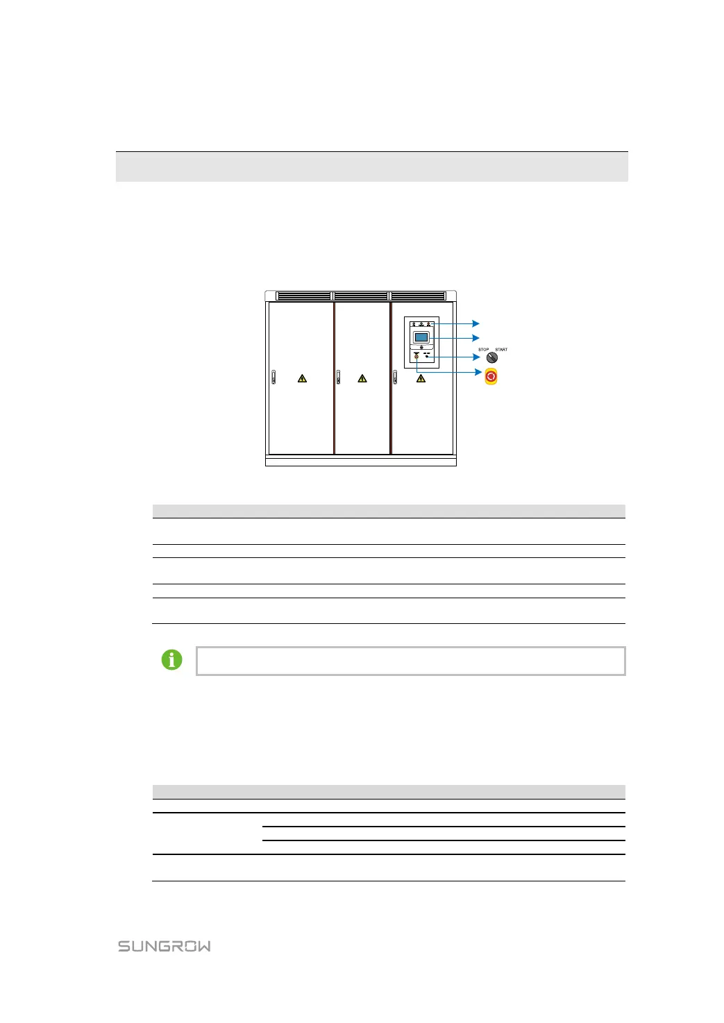
The face and main external components of the inverter are shown in the figure below.
Note: The figure takes the standard inverter appearance as an example, and the actual
product may differ.
Separately, power indicator "POWER", operation
indicator "OPERATION", and fault indicator "FAULT"
Displays the data and execute control commands
Can be used to disconnect the AC side power supply
immediately in case of emergency
Used to start/stop the inverter
A total of three, used to open and close the front doors of
the inverter
In addition to the standard configuration, DC/AC meter is optional. The meter can be
an energy meter or voltage meter. Specifically, refer to the actually received device.
3.1.2 LED Indicators
There are three LED indicators at the upper side of the inverter AC cabinet: POWER,
OPERATION, and FAULT.
These indicators indicate operation status of the inverter. Description of these LED
indicators is as follows.
The control circuit power supply is supplying power.
Inverter is in stop mode.
Inverter is in feed-in operation mode.
Inverter is in alarm run mode*.
A fault occurs and has not been removed.
The LED will be off when the fault is cleared.
 Loading...