12
Symbol Explanation
CGC-SOLAR mark of conformity.
Danger to life due to high voltages!
Only qualified personnel can open and service the inverter.
Disconnect the inverter from all the external power sources before
maintenance!
Burn danger due to the hot surface that may exceed 60°C.
Do not touch live parts for 5 minutes after disconnection from the power
sources.
Read the user manual before maintenance!
* The table shown here is for reference only. The actual product received may differ.
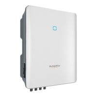
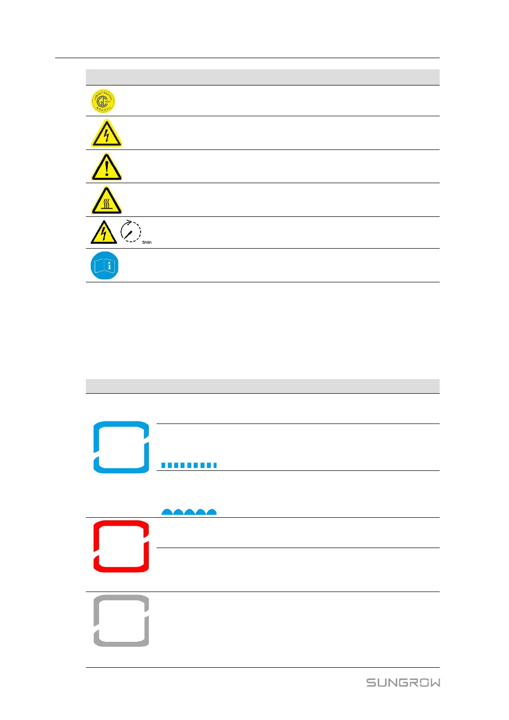
2.4 LED Indicator
The LED indicator on the front of the inverter indicates the working state of the inverter.
table 2-1 LED Indicator State Description
LED Color State Definition
Blue
On
The device is connected to the grid and operating
normally.
Fast blink
(Period: 0.2s)
The Bluetooth connection is established, and there is
data communication.
No system fault occurs.
Slow blink
(Period: 2s)
The device is in standby or startup state (not feeding
power into the grid).
Red
On
A fault occurs and the device cannot connect to the
grid.
Blink
The Bluetooth connection is established, data commu-
nication in process, and a system fault occurs.
Gray
OFF
Both the AC and DC sides are powered down.
2 Product Description User Manual
 Loading...