36
The cable colors in figures in this manual are for reference only. Please select ca-
bles according to local cable standards.
5.2 Terminal Description
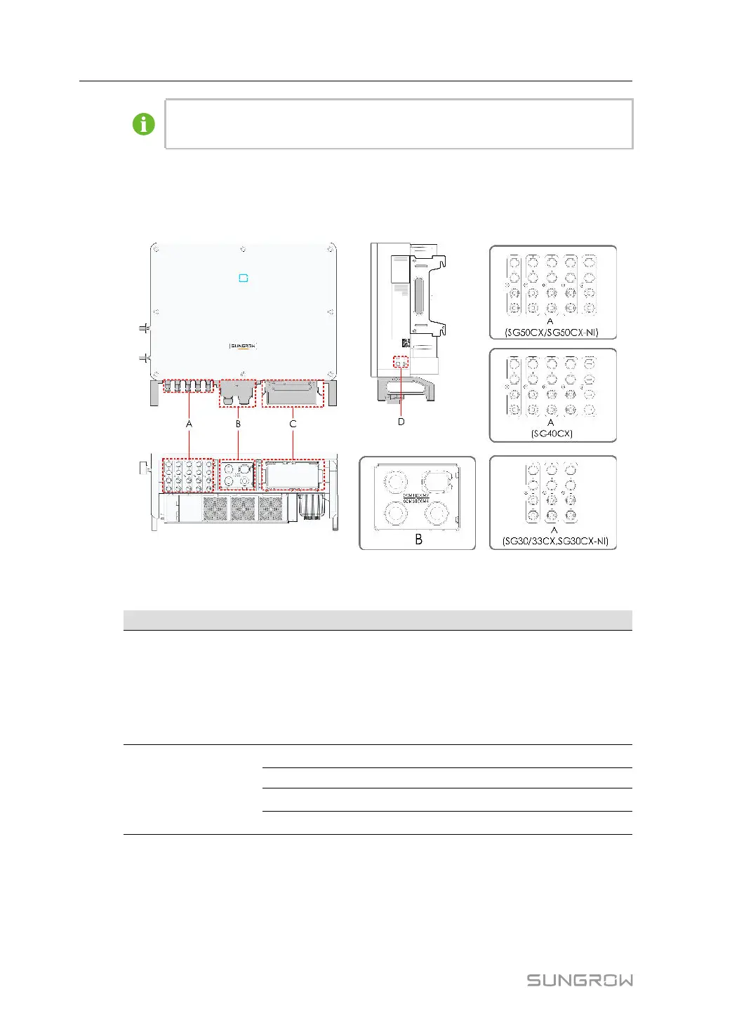
All electrical terminals are located at the bottom of the inverter.
figure 5-1 Terminal Description
* The image shown here is for reference only. The actual product received may differ.
Item Terminal Mark Note
A PV terminals + / -
MC4 PV connector
SG30CX, SG30CX-NI, SG33CX: 6 pairs of
terminals
SG40CX: 8 pairs of terminals
SG50CX, SG50CX-NI: 10 pairs of terminals
B
Communica-
tion terminal
COM1
For RS485 communication wiring.
COM2 For Communication module connection.
COM3
For digital input and output DI/DO wiring.
COM4
For DRM communication wiring.
5 Electrical Connection User Manual
 Loading...