41
5.5.1 External Protective Grounding Requirements
All non-current carrying metal parts and device enclosures in the PV power system should
be grounded, for example, brackets of PV modules and inverter enclosure.
When there is only one inverter in the PV system, connect the external protective grounding
cable to a nearby grounding point.
When there are multiple inverters in the PV system, connect the external protective ground-
ing terminals of all inverters and the grounding points of the PV module brackets to ensure
equipotential connections to ground cables (according to the onsite conditions).
5.5.2 Connection Procedure
Step 1 Prepare the cable and OT/DT terminal, refer to " Crimp OT/DT terminal".
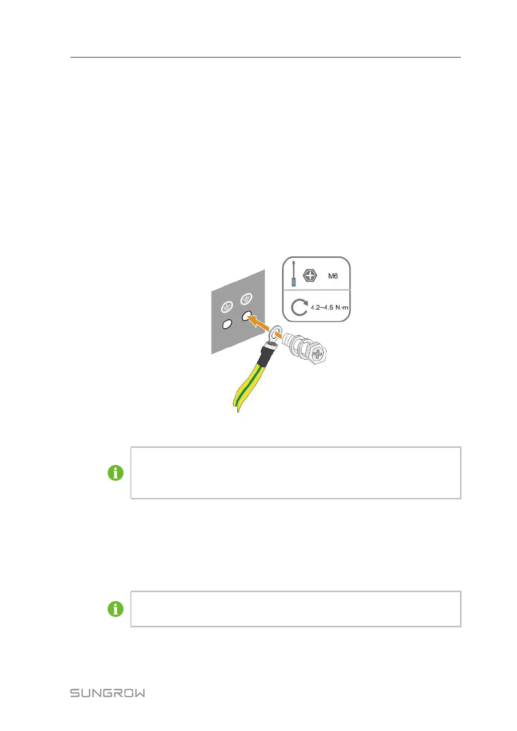
Step 2 Remove the screw on the grounding terminal and fasten the cable with a screwdriver.
Step 3 Apply paint to the grounding terminal to ensure corrosion resistance.
The grounding screws have been anchored to the side of the inverter before deliv-
ery, and do not need to be prepared.
There are two grounding terminals. Use one of them to ground the inverter.
- - End
5.6 AC Cable Connection
5.6.1 AC Side Requirements
Only with the permission of the local grid department, the inverter can be con-
nected to the grid.
User Manual 5 Electrical Connection
 Loading...