13
Voltage may still be present in AC side circuits after the indicator is off. Pay atten-
tion to the electricity safety when operating.
2.5 DC Switch
The DC switch is used to disconnect the DC current safely whenever necessary.
The SG30CX-NI and SG50CX-NI is not equipped with DC switch.
The SG30CX and SG33CX is equipped with one DC switch to control the connection and
disconnection of all DC terminals.
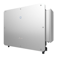
The SG40CX and SG50CX are equipped with two DC switches separately controlling a
group of DC inputs. The correspondence is as follows:
* The image shown here is for reference only. The actual product received may differ.
Turn the DC switches to the ON position before restarting the inverter.
2.6 Circuit Diagram
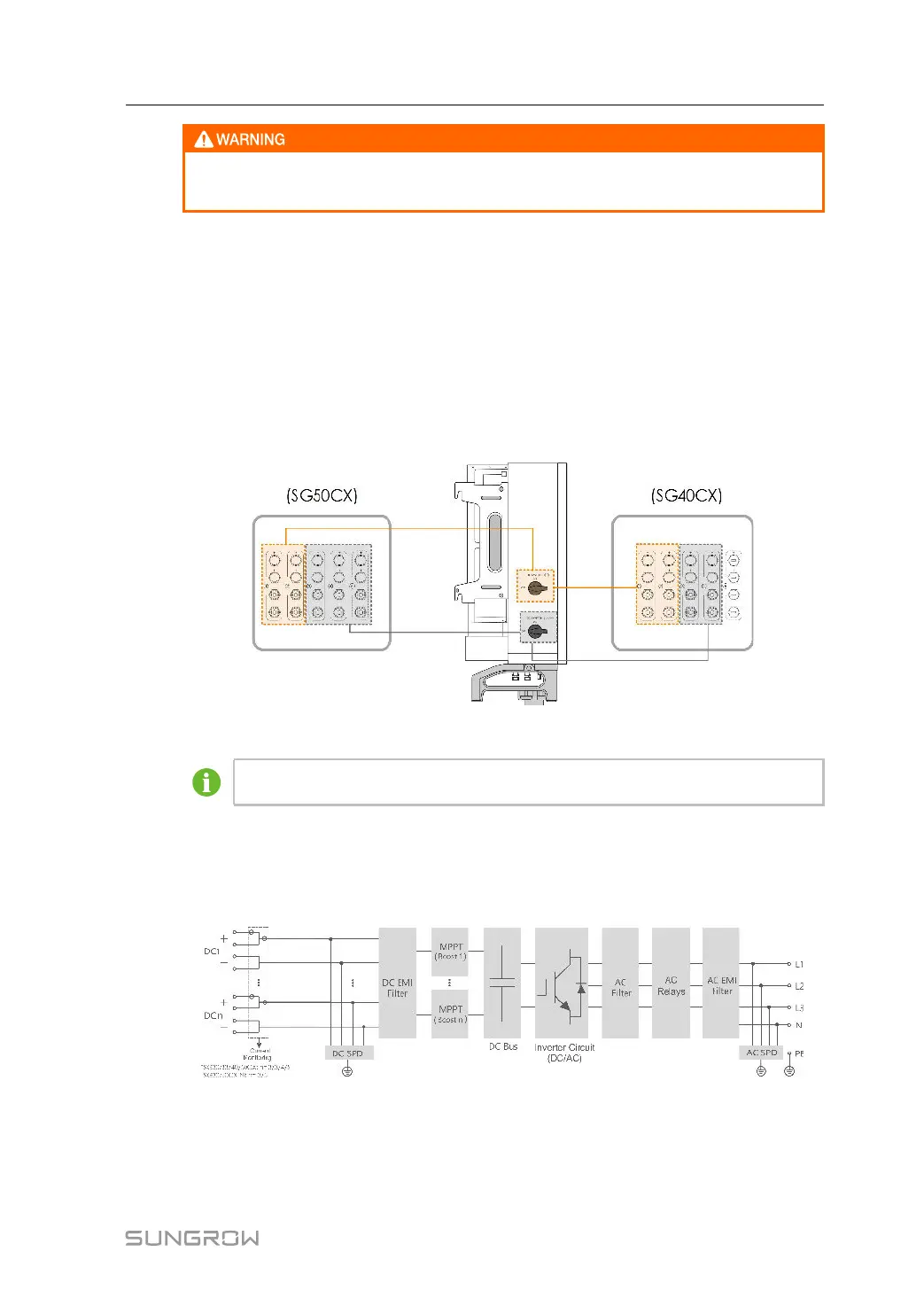
The following figure shows the main circuit of the inverter.
figure 2-4 Circuit Diagram
• The DC SPD provides a discharge circuit for the DC side overvoltage to prevent it from
damaging the internal circuits of the inverter.
User Manual 2 Product Description
 Loading...