53
During installation, firmly press the junction box to ensure that the pin can be in-
serted successfully.
Never hit the pin with a heavy object, such a hammer. Otherwise, it will be irrecov-
erably damaged.
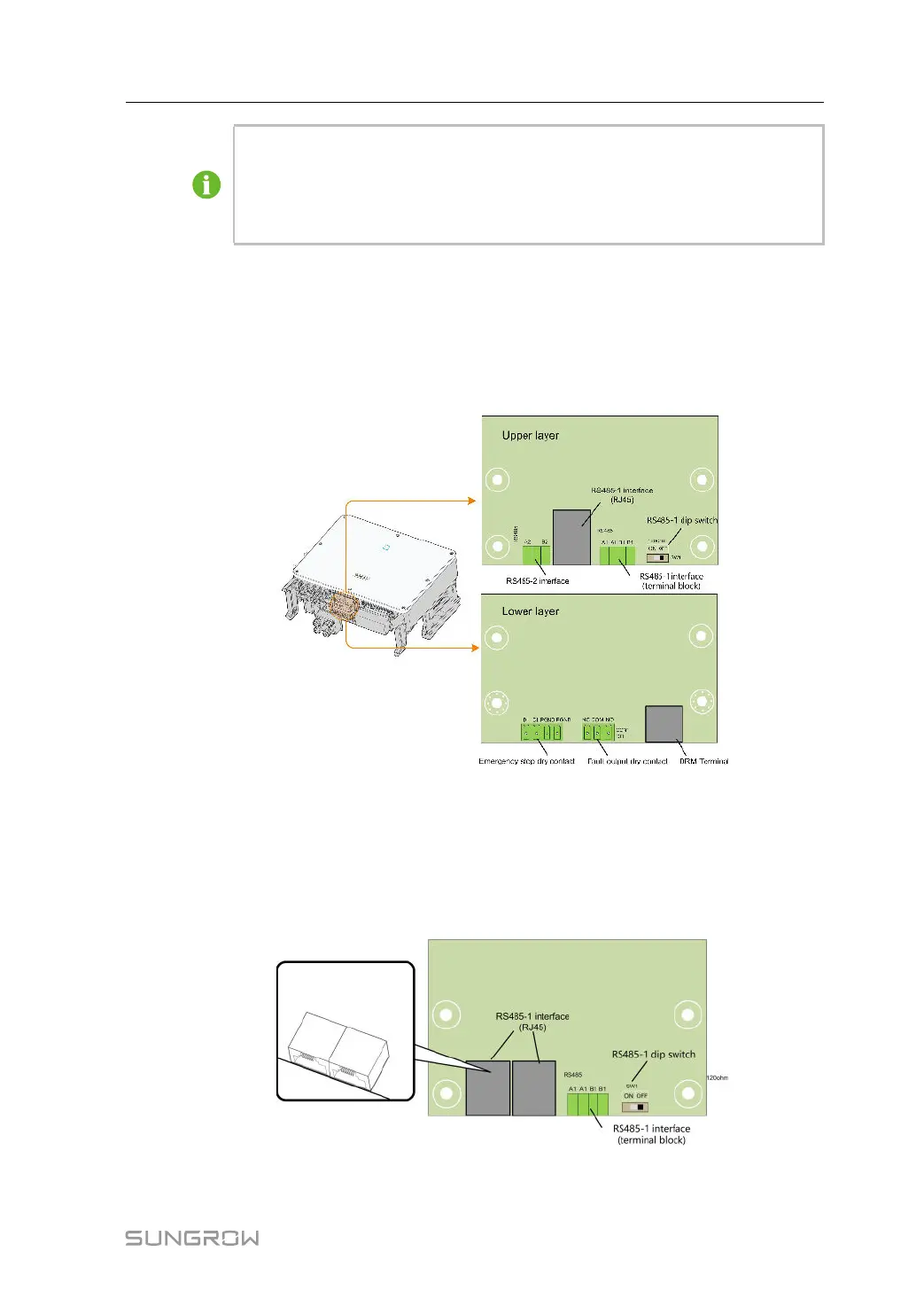
5.9 Communication Wiring Board
The communication board of the inverter includes two layers. The upper layer communica-
tion board mainly includes RS485 communication interfaces while the lower layer communi-
cation board mainly includes DI/DO interface and DRM interface.
5.10 RS485 Connection
5.10.1 Interface Description
As shown in the Figure below, the inverter is equipped with three RS485 communication in-
terfaces and one dip switch.
All three interfaces can be connected to a data acquisition device (Data Logger), to achieve
data exchange with PC or other monitoring devices.
User Manual 5 Electrical Connection
 Loading...