ENGINE 3-51
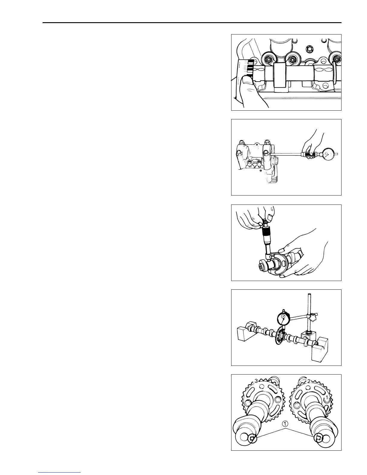
CAMSHAFT SPROCKETS
The fixed position of each camshaft sprocket is determined by
arrow mark “3” for the intake camshaft, and by arrow marks “1”
and “2” for the exhaust camshaft, as located in reference to the
notch 1 on the right end of each camshaft.
Inspect the teeth of each camshaft sprocket for wear or damage.
If they are worn or damaged, replace the sprockets and cam chain
as a set.
NOTE:
Do not rotate the camshafts with the plastigauge in place.
Remove the camshaft journal holders and measure the width of
the compressed plastigauge using the envelope scale. This mea-
surement should be taken at the widest part of the compressed
plastigauge.
If the camshaft journal oil clearance exceeds the limit, measure
the inside diameter of the camshaft journal holder and the out-
side diameter of the camshaft journal. Replace the camshaft or
the cylinder head depending upon which one exceeds the speci-
fication.
" 09900-20602: Dial gauge (1/1000 mm)
09900-22403: Small bore gauge (18 – 35 mm)
# Camshaft journal holder I.D. (IN & EX)
Standard: 22.012 – 22.025 mm (0.8666 – 0.8671 in)
" 09900-20205: Micrometer (0 – 25 mm)
# Camshaft journal O.D. (IN & EX)
Standard: 21.959 – 21.980 mm (0.8645 – 0.8654 in)
CAMSHAFT RUNOUT
Measure the runout using the dial gauge. Replace the camshaft
if the runout exceeds the limit.
" 09900-20606: Dial gauge (1/100 mm)
09900-20701: Magnetic stand
09900-21304: V-block set (100 mm)
# Camshaft runout (IN & EX)
Service Limit: 0.1 mm (0.004 in)
IN.
EX.

 Loading...

