3-64 ENGINE
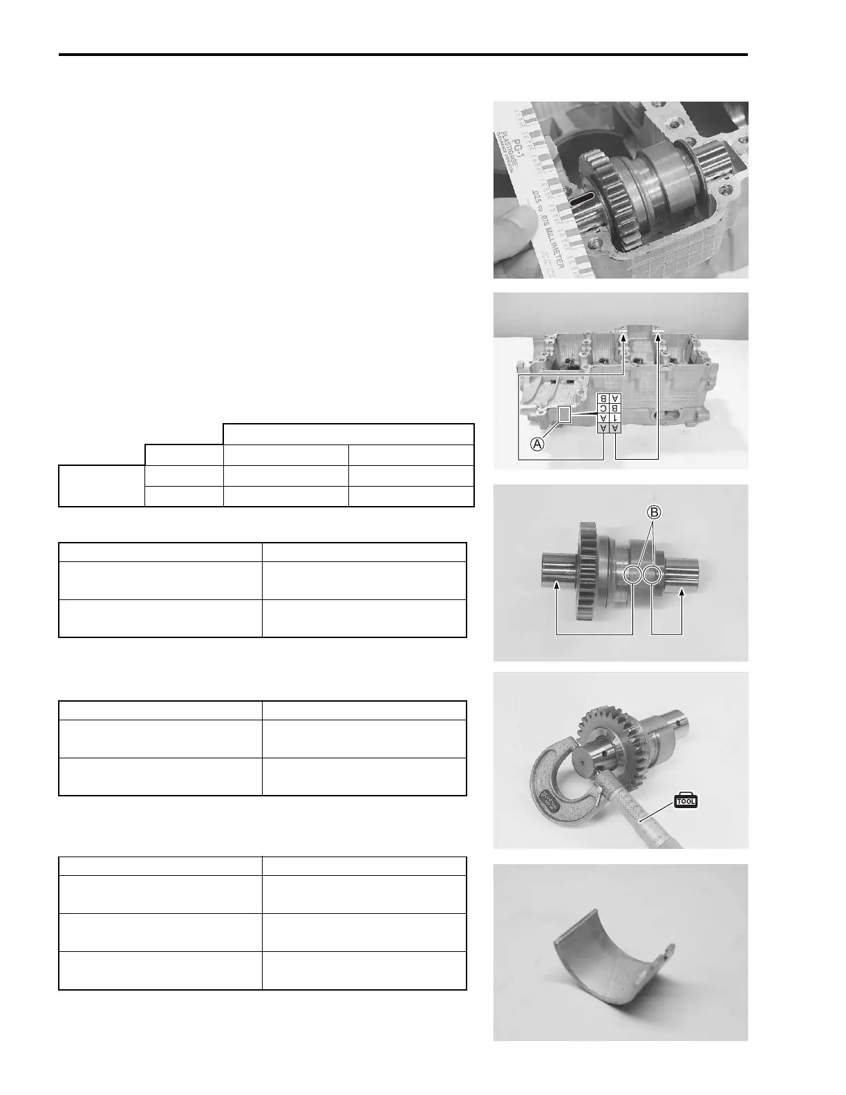
• Remove the middle crankcase and measure the width of the
compressed plastigauge using the envelope scale. This mea-
surement should be taken at the widest part of the com-
pressed plastigauge.
Balancer shaft journal oil clearance:
Standard: 0.028 – 0.052 mm (0.0011 – 0.0020 in)
Service Limit: 0.080 mm (0.031 in)
• If the oil clearance exceeds the service limit, select the speci-
fied bearings from the bearing selection table.
• Check the corresponding crankcase journal I.D. code number
A, “A” or “B” which is stamped on the rear of upper crank-
case.
• Check the corresponding balancer shaft journal O.D. code
number B, “A” or “B” which is stamped on the balancer shaft.
Bearing selection table
Crankcase I.D. specification
Balancer shaft journal O.D. specification
09900-20205: Micrometer (0 – 25 mm)
Bearing thickness specification
NOTE:
The balancer shaft journal bearings on upper and middle crank-
cases are the same.
Balancer shaft journal O.D. B
Code AB
Crankcase
I.D. A
A Green Black
B Black Brown
Code I.D. specification
A
26.000 – 26.008 mm
(1.0236 – 1.0239 in)
B
26.009 – 26.016 mm
(1.0240 – 1.0243 in)
Code O.D. specification
A
22.984 – 22.992 mm
(0.9049 – 0.9052 in)
B
22.976 – 22.984 mm
(0.9046 – 0.9049 in)
Color (Part No.) Thickness
Green
(12229-40F50-0A0)
1.486 – 1.490 mm
(0.0585 – 0.0587 in)
Black
(12229-40F50-0B0)
1.490 – 1.494 mm
(0.0587 – 0.0588 in)
Brown
(12229-40F50-0C0)
1.494 – 1.498 mm
(0.0588 – 0.0590 in)
SAMPLE

 Loading...


