5-22 FUEL SYSTEM AND THROTTLE BODY
AIR CLEANER BOX INSTALLATION
Installation is in the reverse order of removal. Pay attention to
the following points:
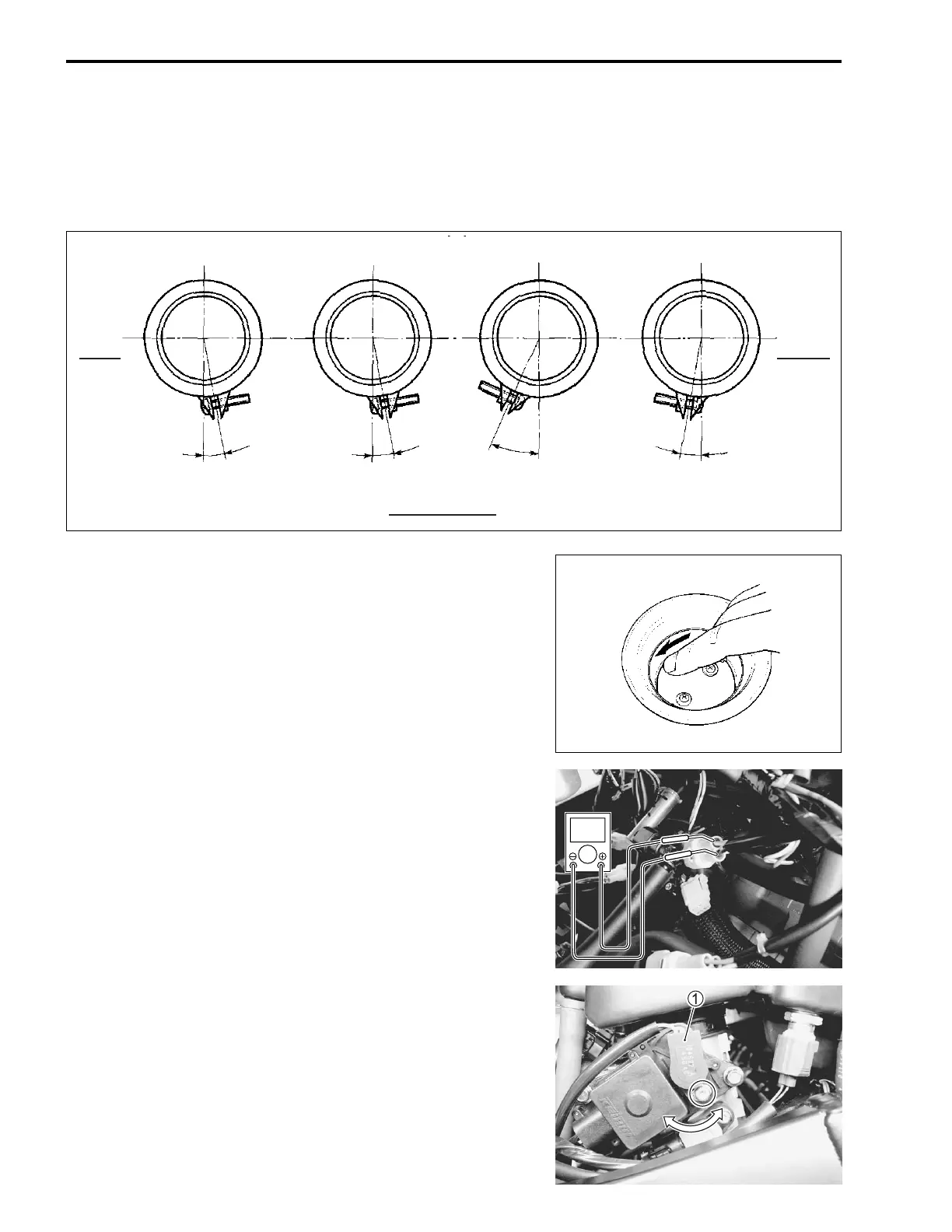
• Install the air cleaner box and tighten the throttle body clamp
screws as shown in the illustration.
STP SENSOR ADJUSTMENT
If the STP sensor adjustment is necessary, measure the sensor
output voltage and adjust the STP sensor position as follows:
• Disconnect the STVA lead wire coupler.
• Remove the air cleaner box cover. (2-4)
• Insert the needle pointed probes to the STP sensor coupler.
• Turn the ignition switch ON.
• Close the secondary throttle valve by finger, and measure the
STP sensor output voltage.
STP sensor output voltage
ST valve is fully closed: 0.48 – 0.52 V
(+ Yellow – - Black)
09900-25008: Multi-circuit tester set
09900-25009: Needle pointed probe set
Tester knob indication: Voltage ()
• Loosen the STP sensor mounting screw.
• Adjust the STP sensor 1 until resistance comes to specifica-
tion and tighten the STP sensor mounting screw.
09930-11950: Torx wrench
STP sensor mounting screw: 3.5 N·m (0.35 kgf-m, 2.5 lb-ft)
#1
#2
#3
#4
10˚ ± 10˚
30˚ ± 10˚
10˚ ± 10˚10˚ ± 10˚
VIEW OF TOP
LEFT
SIDE
RIGHT
SIDE
V
SAMPLE

 Loading...


