Home
Suzuki
Motorcycle
GSX-R1000K5
Suzuki GSX-R1000K5 User Manual
5
of 1
of 1 rating
525 pages
Give review
Manual
Specs
To Next Page
To Next Page
To Previous Page
To Previous Page
Loading...
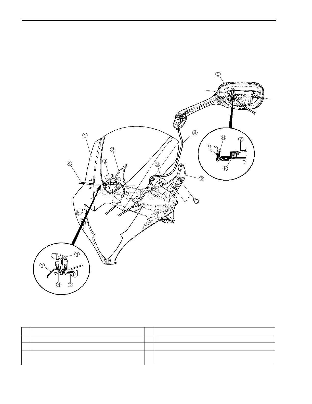
10-38 SERVICING INFORMATION
REAR VIEW MIRROR INSTALLATION
1
Body cowling
5
T
ur
n signal lead wire coupler
2
Cowling brace
6
Mirror cov
er
3
Cushion
7
Mirror body
4
T
ur
n signal lead wire
*A
Locate the tur
n signal lead wire coupler
5
between the mirror co
ver
6
and mirror body
7
.
*A
SAMPLE
491
493
Table of Contents
Foreword Group Index
3
Table of Contents
3
How to Use this Manual
4
Abbreviations Used in this Manual
6
General Information 1
9
General Precautions
10
Warning/Caution/Note
10
Serial Number Location
12
Suzuki Gsx-R1000K5 ('05-Model)
12
Fuel, Oil and Engine Coolant Recommendation
13
Fuel (for Usa and Canada)
13
Fuel (for Other Countries)
13
Engine Oil (for Usa)
13
Engine Oil (for Other Countries)
13
Brake Fluid
13
Front Fork Oil
14
Engine Coolant
14
Water for Mixing
14
Anti-Freeze/Engine Coolant
14
Liquid Amount of Water/Engine Coolant
14
Break-In Procedures
15
Cylinder Identification
15
Information Labels
16
Specifications
17
Dimensions and Dry Mass
17
Engine
17
Drive Train
17
Chassis
18
Electrical
18
Capacities
18
Periodic Maintenance
19
Periodic Maintenance Schedule
20
Periodic Maintenance Chart
20
Lubrication Points
21
Maintenance and Tune-Up Procedures
22
Air Cleaner
22
Spark Plug
23
Valve Clearance
25
Engine Oil and Oil Filter
30
Exhaust Control Valve
31
Fuel Line
32
Engine Idle Speed
32
Throttle Valve Synchronization
33
Evaporative Emission Control System (E-33 Only)
33
Pair (Air Supply) System
33
Throttle Cable Play
33
Clutch
34
Cooling System
35
ENGINE COOLANT Change
35
Engine Coolant Level Check
35
Drive Chain
38
Brake
41
Tires
45
Steering
45
Tire Tread Depth
45
Front Fork
46
Rear Suspension
46
Exhaust Pipe Bolt and Nut
47
Chassis Bolts and Nuts
48
Compression Pressure Check
50
Compression Test Procedure
50
Oil Pressure Check
51
Sds Check
52
Data at the Time of Racing
53
Engine
55
Engine Components Removable with Engine in Place
56
Engine Removal and Installation
57
Engine Removal
57
Engine Installation
64
Engine Disassembly
69
Engine Components Inspection and Service
81
Cylinder Head Cover
81
Cmp Sensor
81
Pair Reed Valve
81
Camshaft
82
Camshaft Runout
84
Cam Chain Tension Adjuster
84
Cam Chain Tensioner
85
Cam Chain Guide
85
Cylinder Head and Valve
85
Clutch
97
Clutch Lifter
99
Oil Pump
100
Starter Clutch
101
Generator
101
Water Pump
102
Gearshift System
102
Oil Pressure Regulator
103
Oil Strainer
103
Transmission
104
Cylinder
107
Piston and Piston Ring
108
Piston Diameter
108
Piston Ring Groove Width
109
Piston Ring Thickness
109
Piston Ring End Gap
109
Crankcase
110
Balancer Shaft
117
Balancer Shaft Journal Bearing
117
Crankshaft and Conrod
119
Crankshaft Runout
119
Crankshaft Journal Bearing
123
Crankshaft Thrust Bearing
126
Engine Reassembly
128
Fi System Diagnosis
161
Precautions in Servicing
163
Electrical Parts
163
Fuse
164
Ecm/Various Sensors
164
Electrical Circuit Inspection Procedure
166
Using the Multi-Circuit Tester
169
Fi System Technical Features
170
Injection Time (Injection Volume)
170
Compensation of Injection Time (Volume)
171
Injection Stop Control
171
Fi System Parts Location
172
Fi System Wiring Diagram
174
Ecm Terminal
175
Self-Diagnosis Function
177
User Mode
177
Dealer Mode
178
Tps Adjustment
180
Fail-Safe Function
181
Fi System Troubleshooting
183
Customer Complaint Analysis
183
Visual Inspection
184
Self-Diagnostic Procedures
185
Self-Diagnosis Reset Procedure
185
Use of Sds Diagnostic Procedures
186
Use of Sds Diagnosis Reset Procedure
187
Show Data When Trouble (Displaing Data at the Time of Dtc)
188
Malfunction Code and Defective Condition
189
C11" (P0340) Cmp Sensor Circuit Malfunction
193
C12" (P0335) Ckp Sensor Circuit Malfunction
195
C13" (P0105-H/L) Iap Sensor Circuit Malfunction
197
C14" (P0120-H/L) Tp Sensor Circuit Malfunction
203
C15" (P0115-H/L) Ect Sensor Circuit Malfunction
208
C21" (P0110-H/L) Iat Sensor Circuit Malfunction
212
C22" (P1450-H/L) Ap Sensor Circuit Malfunction
216
C23" (P1651-H/L) to Sensor Circuit Malfunction
221
C24" (P0351), "C25" (P0352), "C26" (P0353) or "C27" (P0354) IGNITION SYSTEM MALFUNCTION
224
C28" (P1655) Stv Actuator Circuit Malfunction
225
C29" (P1654-H/L) Stp Sensor Circuit Malfunction
228
C31" (P0705) Gp Switch Circuit Malfunction
233
C32" (P0201), "C33" (P0202), "C34" (P0203) or "C35" (P0204) PRIMARY FUEL INJECTOR CIRCUIT MALFUNCTION
235
C36" (P1764), "C37" (P1765), "C38" (P1766) or "C39" (P1767) SECONDARY FUEL INJECTOR CIRCUIT MALFUNCTION
237
C41" (P0230-H/L) Fp Relay Circuit Malfunction
239
C42" (P01650) Ig Switch Circuit Malfunction
241
C46" (P1657-H/L or P1658) EXCV ACTUATOR CIRCUIT MALFUNCTION
242
C49" (P1656) Pair Control Solenoid Valve Circuit Malfunction
251
C60" (P0480) Cooling Fan Relay Circuit Malfunction
253
Sensors
255
Cmp Sensor Inspection
255
Cmp Sensor Removal and Installation
255
Ckp Sensor Inspection
255
Ckp Sensor Removal and Installation
255
Iap Sensor Inspection
255
Iap Sensor Removal and Installation
255
Tp Sensor Inspection
255
Tp Sensor Removal and Installation
255
Tps Adjustment
255
Ect Sensor Inspection
256
Ect Sensor Removal and Installation
256
Iat Sensor Inspection
256
Iat Sensor Removal and Installation
256
Ap Sensor Inspection
256
Ap Sensor Removal and Installation
256
To Sensor Inspection
256
To Sensor Removal and Installation
256
Stp Sensor Inspection
257
Stp Sensor Removal and Installation
257
Stp Sensor Adjustment
257
Fuel System and Throttle Body
258
Fuel System and Throttle
258
Fuel Delivery System
259
Fuel System
260
Fuel Tank Lift-Up
260
Fuel Tank Removal
260
Fuel Tank Installation
261
Fuel Pressure Inspection
261
Fuel Pump Inspection
262
Fuel Discharge Amount Inspection
262
Fuel Pump Relay Inspection
263
Fuel Pump and Fuel Filter Removal
264
Fuel Mesh Filter Inspection and Cleaning
266
Fuel Pump and Fuel Mesh Filter Installation
266
Throttle Body
269
Construction
269
Air Cleaner Box Removal
270
Throttle Body Removal
271
Throttle Body Disassembly
272
Throttle Body Cleaning
274
Inspection
274
Throttle Body Reassembly
275
Throttle Body Installation
278
Air Cleaner Box Installation
279
Stp Sensor Adjustment
279
Fuel Injector Removal
280
Fuel Injector Inspection
280
Fuel Injector Installation
280
Fast Idle
281
Fast Idle Adjustment
281
Throttle Valve Synchronization
283
Throttle Position Sensor (Tps) Setting
286
Exhaust System
287
Exhaust System
288
Exhaust Control System
288
Operation
289
Excva (Exhaust Control Valve Actuator) and Excv (Exhaust Control Valve)
290
Excva Removal
290
Excva Installation
292
Excva Inspection
294
Excv Cable Replacement
294
Excva Adjustment
296
Excv/Muffler Removal
299
Excv Inspection
300
Excv/Muffler Installation
300
Exhaust Pipe Removal
301
Exhaust Pipe Installation
301
Cooling and Lubrication System
303
Engine Coolant
304
Cooling Circuit
305
Cooling Circuit Inspection
305
Radiator and Water Hoses
306
Radiator Removal
306
Radiator Cap Inspection
306
Radiator Inspection and Cleaning
306
Radiator Installation
307
Water Hose Inspection
307
Cooling Fan
308
Removal
308
Inspection
308
Installation
308
Cooling Fan Relay Inspection
309
Ect Sensor
309
Removal
309
Inspection
309
Installation
310
Thermostat
311
Removal
311
Inspection
311
Installation
312
Water Pump
313
Removal and Disassembly
313
Inspection
315
Reassembly and Installation
316
Lubrication System
319
Oil Pressure
319
Oil Filter
319
Oil Pressure Regulator
319
Oil Strainer
319
Oil Jet
319
Oil Pump
319
Oil Pressure Switch
319
Oil Cooler
319
Engine Lubrication System Chart
321
Oil Pan
321
Engine Lubrication System
322
Chassis
324
Exterior Parts
326
Fastener Removal and Installation
326
Screen
328
Body Cowling Cover and Lower Bracket Cover
328
Under Cowling
328
Body Cowling
329
Air Intake Pipe
330
Cowling Brace
330
Front Seat
330
Fuel Tank Lower Side Cover
330
Rear Seat and Seat Tail Cover
331
Frame Cover
331
Front Wheel
332
Construction
332
Removal
333
Inspection and Disassembly
334
Reassembly and Installation
336
Front Fork
340
Construction
340
Removal and Disassembly
341
Inspection
344
Reassembly
345
Installation
349
Suspension Setting
349
Steering Damper
351
Construction
351
Removal
352
Inspection
352
Installation
352
Steering
353
Construction
353
Removal
354
Inspection and Disassembly
355
Reassembly
356
Installation
356
Steering Tension Adjustment
358
Handlebars
359
Construction
359
Removal
359
Installation
360
Rear Wheel
363
Construction
363
Removal
364
Inspection and Disassembly
365
Reassembly and Installation
367
Rear Shock Absorber
371
Construction
371
Removal
372
Inspection
372
Rear Shock Absorber Disposal
373
Installation
374
Suspension Setting
374
Rear Suspension
375
Construction
375
Removal
376
Inspection and Disassembly
378
Reassembly
381
Installation
383
Final Inspection and Adjustment
384
Front Brake
385
Construction
385
Brake Pad Replacement
386
Brake Fluid Replacement
387
Caliper Removal
388
Caliper Disassembly
388
Caliper Inspection
389
Caliper Reassembly
389
Caliper Installation
390
Brake Disc Inspection
391
Master Cylinder Removal and Disassembly
392
Master Cylinder Inspection
393
Master Cylinder Reassembly
394
Master Cylinder Installation
395
Rear Brake
396
Construction
396
Brake Pad Replacement
397
Brake Fluid Replacement
398
Caliper Removal
398
Caliper Disassembly
399
Caliper Inspection
399
Service Limit
399
Caliper Reassembly
400
Caliper Installation
401
Master Cylinder Removal
402
Master Cylinder Disassembly
402
Master Cylinder Inspection
403
Master Cylinder Reassembly
403
Master Cylinder Installation
404
Tire and Wheel
405
Tire Removal
405
Inspection
405
Valve Inspection
406
Tire Installation
407
Balancer Weight Installation
408
Drive Chain
409
Drive Chain Cutting
409
Drive Chain Connecting
410
Electrical System
413
Cautions in Servicing
415
Connector
415
Coupler
415
Clamp
415
Fuse
415
Semi-Conductor Equipped Part
416
Battery
416
Connecting the Battery
416
Wiring Procedure
416
Using the Multi-Circuit Tester
417
Location of Electrical Components
418
Charging System
420
Troubleshooting
420
Inspection
421
Starter System and Side-Stand/Ignition Interlock System
424
Troubleshooting
424
Starter Motor Removal
425
Starter Motor Disassembly
426
Starter Motor Inspection
426
Starter Motor Reassembly
427
Starter Relay Inspection
428
Side Stand/Ignition Interlock System Parts Inspection
429
Ignition System
432
IMMOBILIZER (Except for E-03, 28, 33)
433
Troubleshooting
435
Inspection
437
Combination Meter
441
Description
441
Removal and Disassembly
442
Inspection
443
Lamps
447
Headlight, Brake Light/Taillight, License Plate Light and Turn Signal Light
447
Relays
449
Turn Signal/Side-Stand Relay
449
Starter Relay
449
Fuel Pump Relay
449
Cooling Fan Relay
449
Ignition Switch Removal
450
Ignition Switch Installation
450
Switches Inspection
451
Battery
452
Specifications
452
Initial Charging
452
Servicing
454
Recharging Operation
454
Servicing Information
455
Troubleshooting
457
Fi System Malfunction Code and Defective Condition
457
Engine
461
Radiator (Cooling System)
467
Chassis
468
Brakes
469
Electrical
470
Battery
471
Wiring Harness, Cable and Hose Routing
472
Wiring Harness Routing
472
Cable Routing
475
Throttle Body Hose Routing
476
Fuel Tank Drain Hose Routing
477
Cooling System Hose Routing
478
Front Brake Hose Routing
479
Rear Brake Hose Routing
480
Pair (Air Supply) System Hose Routing
481
Fuel Tank Installation
482
Fuel Tank Lower Side Cover Cushion Rubber
483
Fastener Installation
483
Cowling Installation
484
Frame Cover Installation
485
Seat Lock Cable Routing
485
Rear Fender Installation
486
Under Cowling Heat Shield Installation
487
Body Cowling Cover Cushion Installation
488
Windscreen Tape Cushion Installation
488
Headlight Tape Cushion Installation
489
Air Intake Cover Tape Cushion Installation
489
Side-Stand Installation
490
Gearshift Pedal Installation
490
Handlebar Balancer
491
Front Footrest Installation
491
Rear View Mirror Installation
492
Rear Combination Light Installation
493
Regulator/Rectifier Installation
494
Special Tools
495
Tightening Torque
499
Engine
499
Fi System and Intake Air System
500
Cooling System
500
Chassis
501
Tightening Torque Chart
502
Service Data
503
Emission Control Information
513
Emission Control Systems
514
Fuel Injection System
514
Crankcase Emission Control System
515
Exhaust Emission Control System (Pair System)
516
Noise Emission Control System
517
Inspection
518
Pair Hoses
518
Pair Reed Valve
518
Pcv Hose
518
Pair Control Solenoid Valve
518
Pair (Air Supply) System and Emission Control System
518
Pair (Air Supply) System Diagram
520
Pair (Air Supply) System Hose Routing
521
Wiring Diagram
522
5
Based on 1 rating
Ask a question
Give review
Questions and Answers:
Need help?
Do you have a question about the Suzuki GSX-R1000K5 and is the answer not in the manual?
Ask a question
Suzuki GSX-R1000K5 Specifications
General
Brand
Suzuki
Model
GSX-R1000K5
Category
Motorcycle
Language
English
Related product manuals
Suzuki GSX-R1000/A
151 pages
Suzuki 1987 GSX-R150
311 pages
Suzuki GSX-R750
659 pages
Suzuki GSX-R600
653 pages
Suzuki GSX-R 400
26 pages
Suzuki GSX-R 1100
57 pages
Suzuki GSX-R600 2007
522 pages
Suzuki GSX-R600 2006
522 pages
Suzuki GSX-R750W 1993
352 pages
Suzuki GSX-R750K2 2002
495 pages
Suzuki GSX R 1100 1991
57 pages
Suzuki GSX-R750K1 2001
495 pages

 Loading...


