8-26 CHASSIS
INSTALLATION
Install the front fork in the reverse order of removal. Pay atten-
tion to the following points:
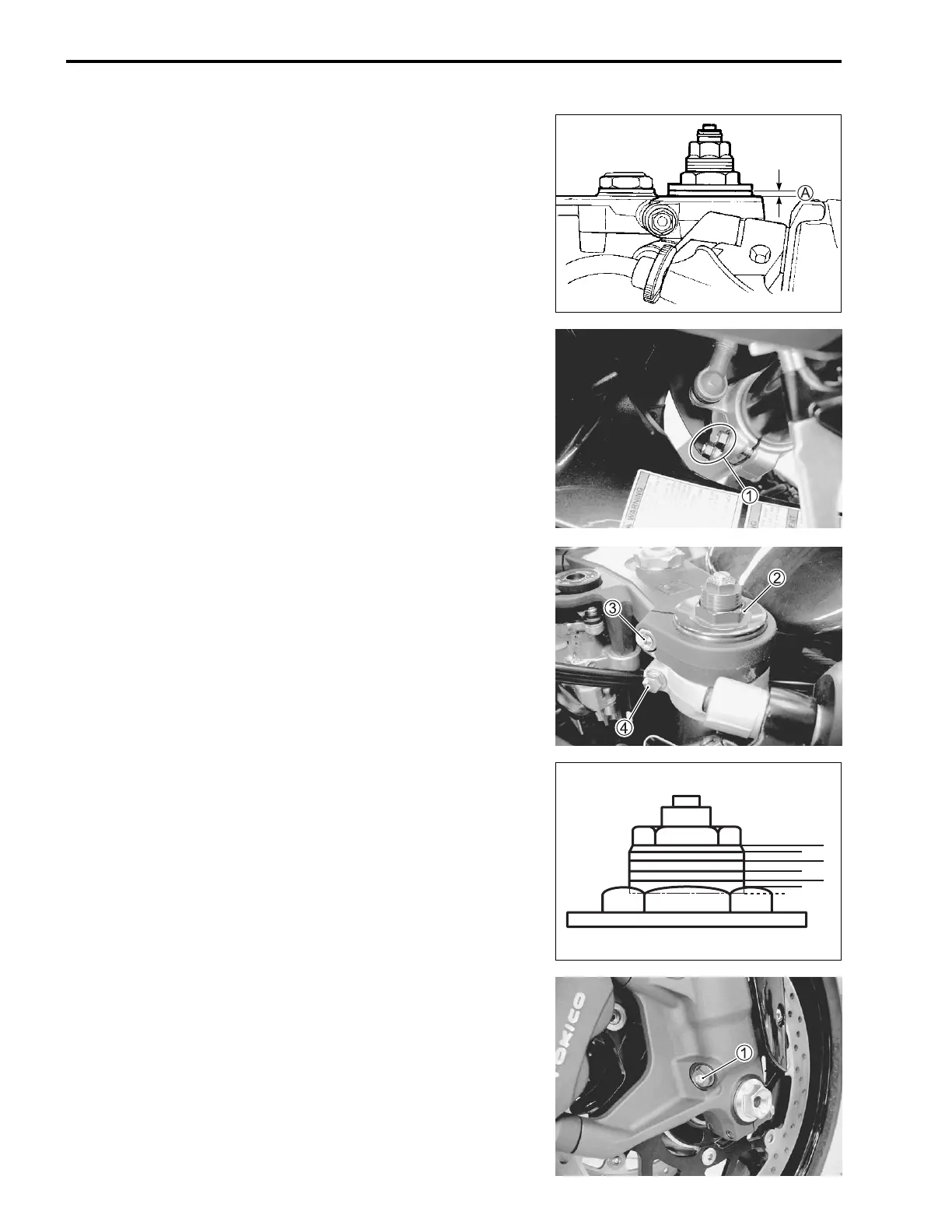
• Set the upper surface of the outer tube height A at 4.0 mm
(0.157 in) from the upper surface of the steering stem upper
bracket and tighten the front fork lower clamp bolts 1 to the
specified torque.
Front fork lower clamp bolt: 23 N·m (2.3 kgf-m, 16.5 lb-ft)
• Tighten the front fork cap bolt 2 to the specified torque and
recheck the front fork outer tube upper surface height A from
the upper surface of the steering stem upper bracket.
Front fork cap bolt: 23 N·m (2.3 kgf-m, 16.5 lb-ft)
• Position the handle bears on the upper bracket. (8-38)
• Tighten the front fork upper clamp bolts 3 and handlebar
clamp bolts 4.
Front fork upper clamp bolt: 23 N·m (2.3 kgf-m, 16.5 lb-ft)
Handlebar clamp bolt: 23 N·m (2.3 kgf-m, 16.5 lb-ft)
• Remount the front wheel. (8-15)
• Cable routing (10-21)
• Front brake hose routing (10-25)
SUSPENSION SETTING
After installing the front fork, adjust the spring pre-load and
damping force as follows.
SPRING PRE-LOAD ADJUSTMENT
There are five grooved lines on the side of the spring adjuster.
Position 0 provides the maximum spring pre-load and position 5
provides the minimum spring pre-load.
STD position: 4
DAMPING FORCE ADJUSTMENT
Compression damping force
Fully turn the damping force adjuster 1 clockwise. It is at stiffest
position and turn it out to standard setting position.
(For E-02, 19): 6 clicks out from stiffest position
(For E-03, 24, 28, 33): 14 clicks out from stiffest position
0
2
4.5
5
3
1
4
SAMPLE

 Loading...


