Appendix A: Specifications
370B User Manual
A-3
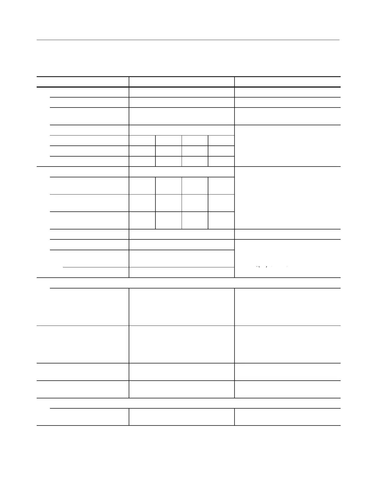
Table A-1: Collector Supply (Cont.)
Characteristic Operating InformationPerformance Requirement
Max peak volts
Max Peak Voltage 16 V, 80 V, 400 V, 2000 V Selected by the MAX PEAK VOLTS buttons.
Voltage accuracy Peak open circuit voltage on all ranges within
+15, -0%
At MAX PEAK POWER of 50 W.
Current Available In PULSE mode of STEP GENERATOR,
a ailable c rrent is t o times of DC mode
Peak Volts 16 V 80 V 400 V 2000 V
ava
a
e curren
s
wo
mes o
mo
e.
Range 10 A 2A 0.4 A 0.05 A
Max Peak Current 20 A 4A 0.8 A 0.1 A
Series Resistance Available Selection of 0.26 W, 1.3 W, 6.4 W,32W, 160
W 800 W 4kW 20 k W 100 k W 500 k W
Min/Max Resistance
Peak Volts Range
16 V 80 V 400 V 2000 V
,
,
,
,
,
,
2.5 M W, 12.5 M W
Minimum
series resistance (W)
0.26 6.4 160 20 k
Maximum
series resistance (W)
800 20 k 500 k 12.5 M,
Resistance Accuracy Within5%or0.2W
Peak power watts Available Derived from nominal peak openĆcircuit
collector oltage and nominal series resist
16, 80 and
400 V range
220 W, 50 W, 10 W, 2 W, 0.4 W, 0.08 W
co
ec
or vo
age an
nom
na
ser
es res
s
Ć
ance values.
P=V*V/
4R
for < 220 W
2000 V range 50 W, 10 W, 2 W, 0.4 W, 0.08 W
P = (V-I*R)*I for 220 W
Variable collector supply
0 - 100.0 % % of maximum peak voltage value is
displayed in the CRT readout area. Provides
uncalibrated variable collector supply
amplitude control from 0 to 100 % in 0.1 %
increments.
Safety interlocks The protective cover must be in place over
test terminals and lid shut before voltage can
be applied to the terminals.
When protective cover is open, collector
supply is not operated.
Warning Indicator Red light indicates dangerous voltage is
applied to collector or base terminal.
Limiting indicator Indicates that internal sensing circuit
automatic protection is operating.
Looping compensation
Range At least 100 pF Cancels stray capacitance between DUT
terminal and ground.
 Loading...