Reference
3-2
370B User Manual
General Description of Instrument Operation
The 370B is a microprocessor-controlled semiconductor tester that displays and
allows measurement of both static and dynamic semiconductor characteristics
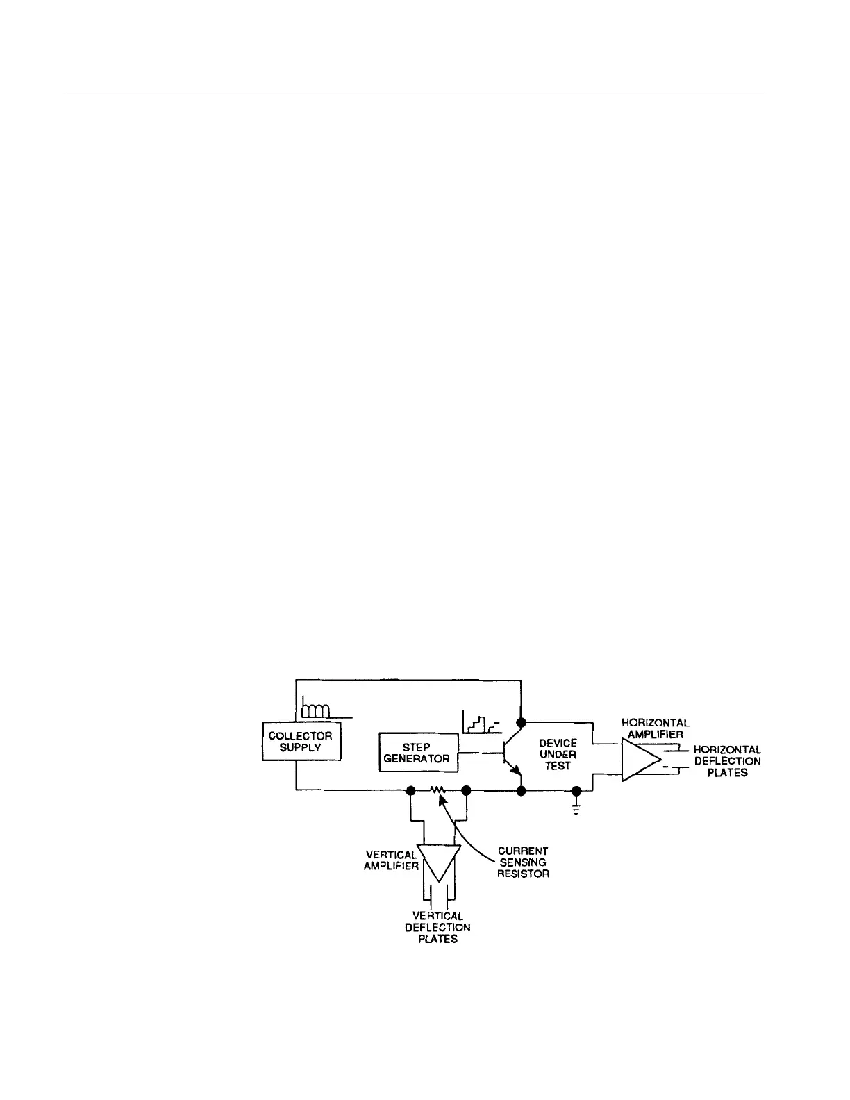
obtained under simulated operating conditions. The Collector Supply and Step
Generator produce voltages and currents that are applied to the device under test.
The display amplifiers measure the effects of these applied conditions on the
device under test. The result is a family of characteristics curves traced on the
CRT.
The Collector Supply circuit normally produces a full-wave rectified sine wave
that can be either positive- or negative-going. The amplitude of the signal can be
varied from 0 to 2000 volts, as determined by the MAX PEAK VOLTS controls
and the VARIABLE COLLECTOR SUPPLY control. The Collector Supply
output is applied to either the collector or the base (or equivalent) terminal of the
device under test. The Step Generator produces ascending steps of current or
voltage at a normal rate of one step per cycle of the Collector Supply. The
amount of current or voltage per step is controlled by the STEP AMPLITUDE
control and the total number of steps is controlled by the NUMBER OF STEPS
controls. This Step Generator output can be applied to either the base or the
emitter (or equivalent) terminals of the device under test. The display amplifiers
are connected to the device under test. These amplifiers measure the effects of
the Collector Supply and of the Step Generator on the device under test, amplify
the measurements and apply the resulting voltages to the deflection plates of the
CRT. Display amplifier sensitivity is controlled by the VERTICAL CURRENT/
DIV control and the HORIZONTAL VOLTS/DIV control. Figure 3–1 is a block
diagram showing the connection of these circuits to the device under test for a
typical measurement.
Figure 3-1: 370B Block Diagram
 Loading...