Getting Started
1-10
370B User Manual
positioned some multiple of 45mm(1.75 in) from the bottom or top, all holes
should line up and no drilling should be required.
The slide–out tracks mount easily to the rack front and rear vertical mounting
rails if the inside distance between the rails is within 503mm (19.8in) to 674mm
(26.5 in). If the tracks are to be installed in a rack having other dimensions,
provide extra support (for example, extensions to the rear mounting brackets) for
the rear ends of the slide–out tracks.
The front rack rails must be at least 432mm(17 in) apart. The front lip of the
stationary–track section mounts in front of the rail.(Use bar nuts behind untapped
front rails.) The front lip of the stationary track section must mount in front of
the front rail to allow the 370B spring latch to function properly.
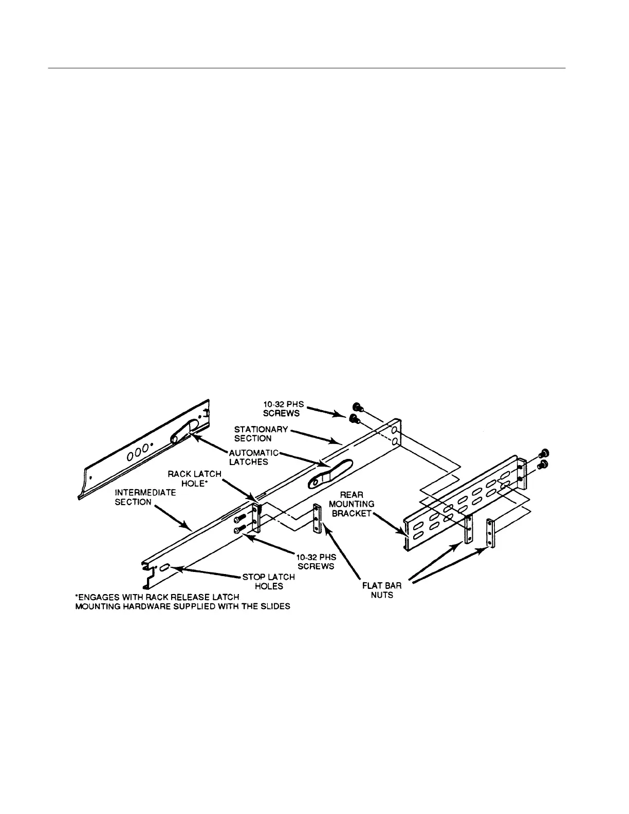
The slide–out tracks consist of two assemblies, one for each side of the
instrument. Each assembly consists of three sections (see Figure 1–5).The
stationary section of each track attaches to rack rails as shown in Figure 1–6. The
chassis section mounts on the instrument and is installed at the factory. The
intermediate section fits between the other two sections, allowing the instrument
to be fully extended out of the rack.
Figure 1-5: Rackmounting Hardware
 Loading...