Operating Basics
370B User Manual
2-25
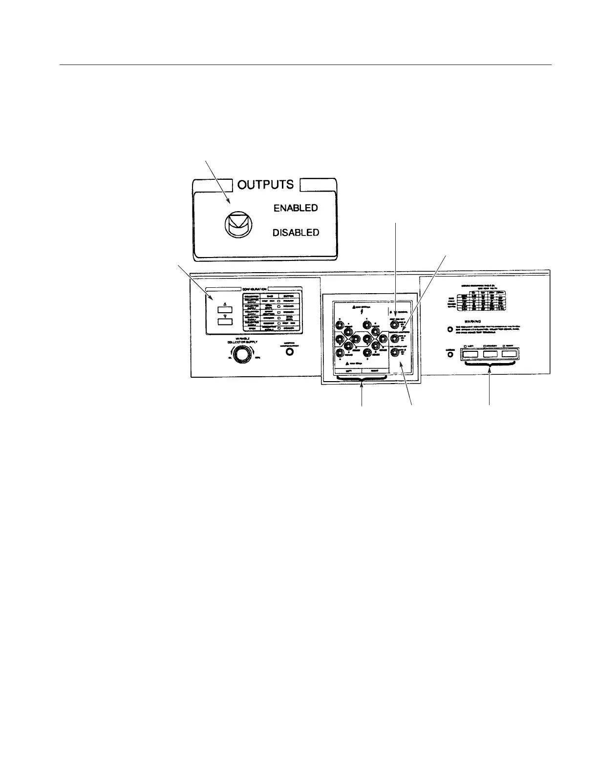
Figure 2–9 shows the signal outputs, connectors configurations, and indicators,
and the input connector.
Figure 2-9: Signal Output Controls and Connectors, Configuration Controls and
Indicators, and Input Connector
OUTPUTS. The OUTPUTS Enables or disables the Collector Supply, Step
Generator, and AUX Supply outputs. Too much current automatically trips the
breaker to disable outputs.
When the breaker disables the outputs, the VARIABLE COLLECTOR SUPPLY,
and therefore the output, is reset to 0%. After enabling the outputs, the VARI-
ABLE COLLECTOR SUPPLY must be reset to the desired level.
Adapter Connector. The Adapter Connector allows the connection of various test
adapters.
LEFT, RIGHT and STANDBY. LEFT, RIGHT and STANDBY controls select the
device to be tested (left or right).
STEP GEN OUT. The Step Generator signal is available at this terminal.
Signal Output Controls
and Connectors,
Configurations and
Indicators, and Input
Connector
 Loading...