Reference
370B User Manual
3-9
12. Change the 370B settings as follows:
Cursor Mode OFF
Collector Supply POLARITY + DC
13. Adjust the trace intensity and turn the VARIABLE COLLECTOR
SUPPLY control clockwise. Note that the display of the forward voltage
diode characteristic is now a spot which indicates, the current conducted by
the diode and the voltage across the diode.
14. Turn the VARIABLE COLLECTOR SUPPLY control counterclockwise.
Note that the spot traces out the diode characteristic curve.
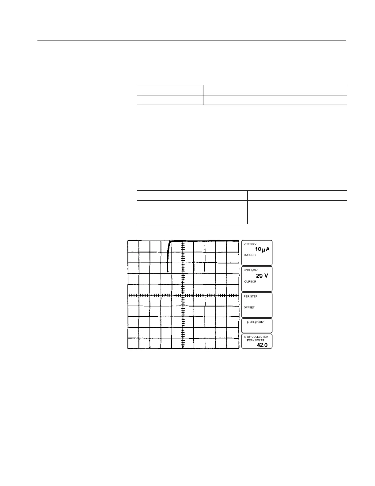
15. Change the 370B settings as follows:
Collector Supply POLARITY - (fullĆwave)
VERTICAL CURRENT/DIV, HORIZONTAL
VOLTS/DIV, and Collector Supply MAX
To appropriate values for the reverse
current and reverse breakdown voltage of
the diode.
Figure 3-4: Display of signal diode reverseĆbias characteristics
16. Rotate the VARIABLE COLLECTOR SUPPLY control clockwise and
adjust the trace intensity. Note the display of the reverse voltage characteris-
tic of the diode (see Figure 3–4).
 Loading...