Operating Basics
2-22
370B User Manual
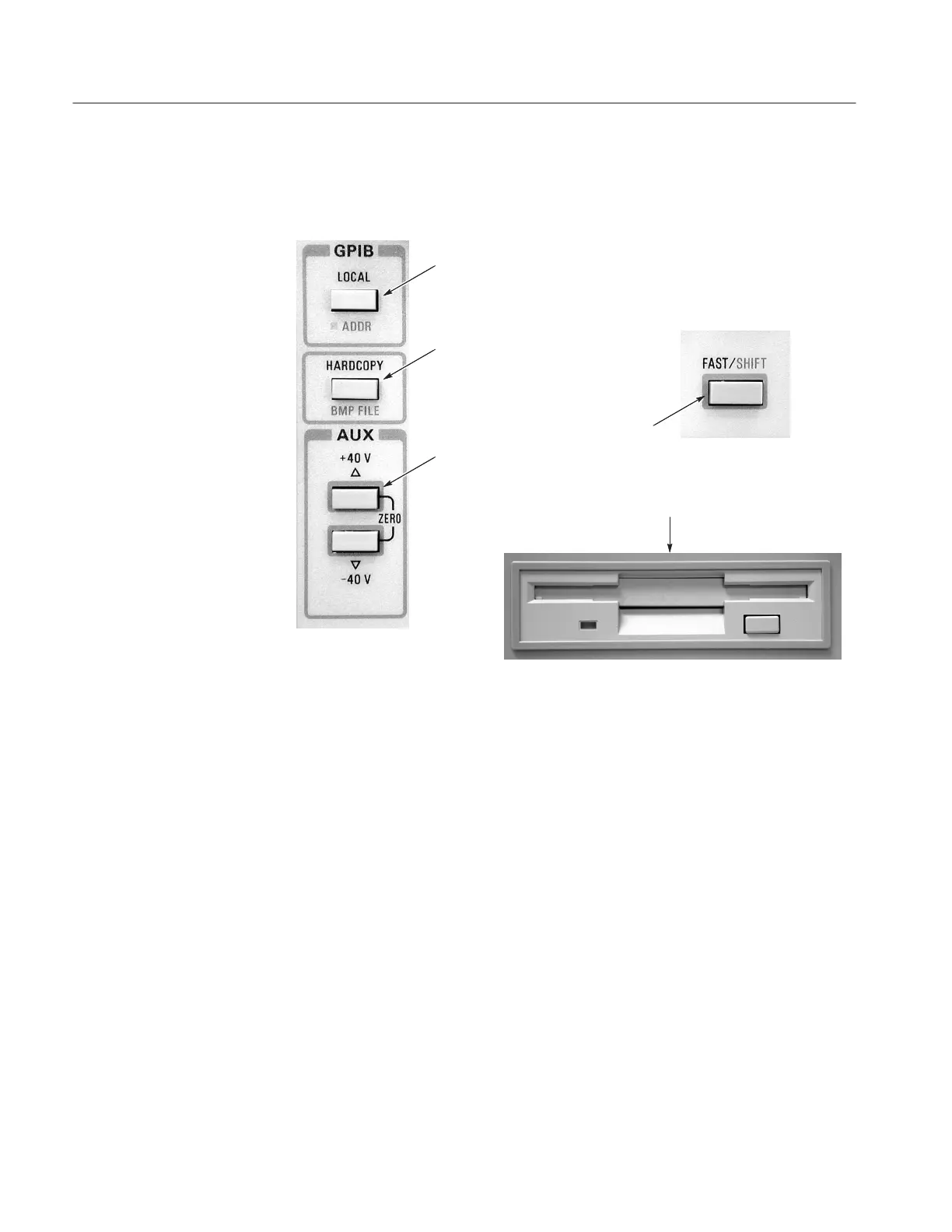
Figure 2–8 shows the AUX supply, GPIB, FAST/SHIFT, and Floppy Disk Drive
controls.
!
Figure 2-8: AUX Supply, GPIB Controls, FAST/SHIFT, and Floppy Disk Drive
AUX. The auxiliary voltage supply produces up to "40 V at up to "10 mA, or
up to "20 V at up to "100 mA. The up and down buttons are used to set the
auxiliary supply output voltage. The output voltage is supplied to the AUX
SUPPLY OUT connector. The auxiliary voltage setting is displayed at the lower
left of the CRT.
Simultaneously pressing the two buttons sets the auxiliary supply to zero volts
and erases the voltage readout.
Holding down the FAST/SHIFT button while press ing either of the AUX
buttons causes voltage changes to be in larger increments.
LOCAL. The LOCAL control changes the operating mode of the 370B from
remote to local. The instrument is placed in remote operation through the GPIB.
When the 370B is under remote control, the REMOTE LED indicator illumi-
nates.
Pressing the LOCAL button while holding down the FAST/SHIFT button causes
the 370B to read the GPIB address and message terminator selections on the
Aux Supply, GPIB,
FAST/SHIFT, and Floppy
Disk Drive Controls
 Loading...