Reference
3-12
370B User Manual
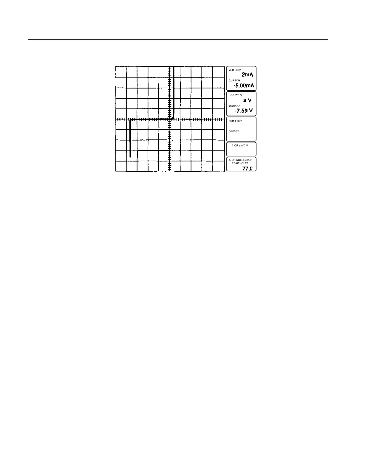
Figure 3-7: Measuring breakdown voltage with the Dot cursor
1. Press the Position DISPLAY button and press RIGHT Position button until
the Zener breakdown portion of the display is within 0.1 division of the
center vertical line. Note that the vertical and horizontal offset values are
displayed at the bottom right of the CRT. Multiply the horizontal offset
readout by the HORIZ/DIV readout to calculate the approximate breakdown
voltage of the Zener diode.
2. Set the MAG control to X10 position. Note that the VERT/DIV and
HORIZ/DIV readout value has changed to indicate the 10 times multiplica-
tion. By expanding the scale, a more precise measurement can be made.
1. Set the OUTPUTS breaker to the DISABLED position, then open the
protective cover.
2. Remove the axial lead adapter (A1005) and replace it with a transistor
adapter (A1007).
3. Place an NPN silicon transistor into the right transistor test socket of the
transistor adapter.
4. Close the protective cover.
5. Observe that the Memory Index is set to 1, then press the Setup RECALL
button to initialize the 370B.
Display Offset and
Magnifier
Step Generator
 Loading...