Reference
3-8
370B User Manual
5. Set the 370B controls as follows:
LEFTĆRIGHTĆSTANDBY RIGHT
VERTICAL CURRENT/DIV To appropriate values and (depending on the HORIZONTAL
VOLTS/DIV forward current and forward voltage rating of the
diode).
CONFIGURATION BASE = SHORT (EMITTER),
EMITTER = COMMON
6. Set the OUTPUTS breaker to the ENABLED position.
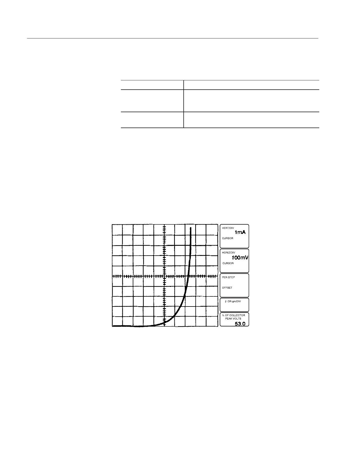
7. Turn the VARIABLE COLLECTOR SUPPLY control clockwise. Note the
display of the forward voltage characteristic of the diode (see Figure 3–3).
8. Use the Cursor selection buttons to select the DOT cursor. A high-intensity
dot will be displayed on the characteristic curve. If the dots not appear,
adjust the NON STORE/STORE/VIEW intensity control.
9. Use the Position Control buttons to move the dot cursor into the on-state
region.
Figure 3-3: Display of signal diode forwardĆbias characteristics
10. Use the Cursor selection buttons to select the f LINE cursor. If the f Line
cursor does not appear, adjust the READOUT/CURSOR intensity control.
11. Use the Position Control buttons to change the slope of the f line cursor until
it is tangent to the curve. The CURSOR (f:1/grad) readout indicates the
on-state resistance of the diode.
 Loading...