Operating Basics
2-20
370B User Manual
MAX PEAK VOLTS. The MAX PEAK VOLTS control selects the maximum peak
volts of the Collector Supply. The LED indicates the selected maximum peak
volts. When the MAX PEAK VOLTS setting is changed, the Collector Supply
output automatically goes to 0 %. When the CONFIGURATION mode is BASE
COLLECTOR SUPPLY, the available MAX PEAK VOLTS setting is v 400 V.
MAX PEAK POWER WATTS. The LED indicates the selected MAX PEAK
POWER WATTS. These controls do not affect the Variable Collector Supply
output. When MAX PEAK VOLTS is set to 2000 V, the available maximum
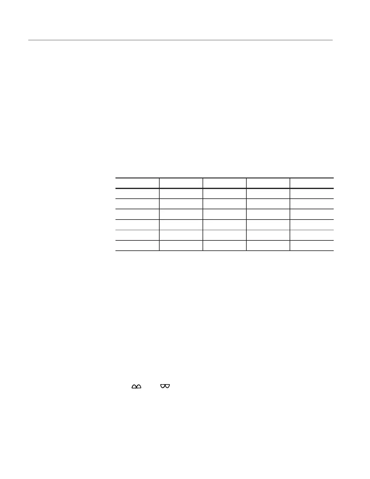
peak power is v50 W. The relationship between MAX PEAK POWER and
SERIES RESISTORS is shown in Table 2–4.
Table 2-4: Max Peak Power vs. Series Resistors
16 V 80 V 400 V 2000 V
W W W
W W W W
W W W W
W W W W
W W W W
W W W W
POLARITY. The LED indicates the selected mode. When the Collector Supply
polarity is changed or switched to or from AC, the Collector Supply output
automatically goes to 0 %. Trace origin is at graticule lower left corner when a
plus mode is selected, at graticule center when AC is selected, and at graticule
upper right corner when a minus mode is selected. Following are the seven
collector supply polarity modes:
+LEAKAGE and -LEAKAGE: Vertical sensitivity is increased 1000 times.
Vertical amplifier measures emitter current. Collector Supply mode is
automatically set for DC voltage output. The number of steps is automatical-
ly set to 0 and the Step Generator output consists of offset only.
+DC and -DC: When +DC or –DC is selected, the collector supply applies a
DC voltage equal to the peak value set by the VARIABLE COLLECTOR
SUPPLY control.
+
and - : When either is selected, a full-wave rectified sine wave of
+ or – polarity, respectively is applied to the collector or base terminals and
either a positive or negative staircase is applied to the base or emitter
terminals from the step generator.
AC: Selecting the ac polarity applies a sinusoidal voltage to the collector or
base terminals. The step generator output is positive-going.
 Loading...