Introduction and Specifications
Electrical Specifications 1
1-19
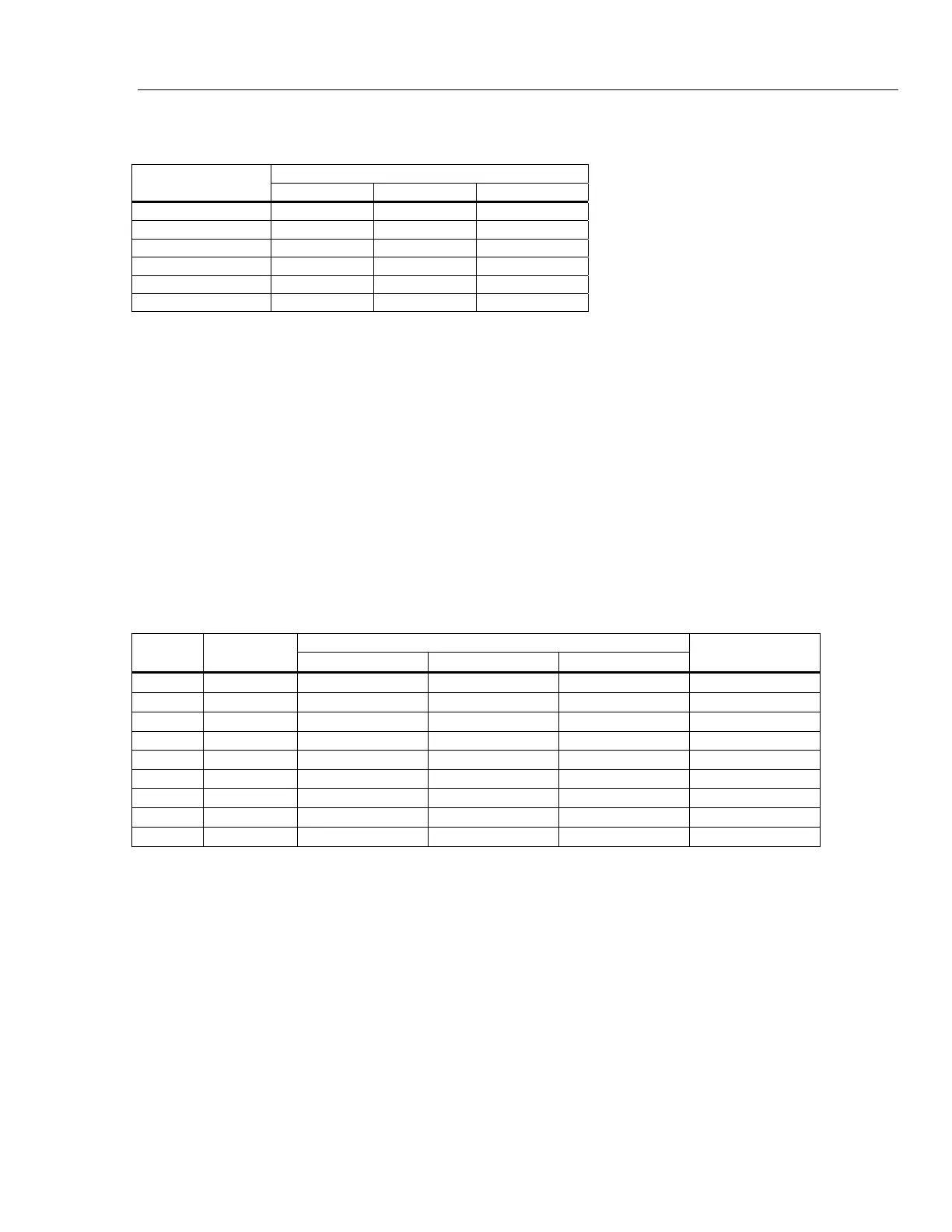
Additional Low Frequency Errors
Error is stated as % of reading.
AC Filter
Frequency
3 HZ (slow) 20 HZ (medium) 200 HZ (fast)
10 – 20 Hz 0 0.25 –
20 – 40 Hz 0 0.02 –
40 – 100 Hz 0 0.01 0.55
100 – 200 Hz 0 0 0.2
200 Hz – 1 kHz 0 0 0.02
>1 kHz 0 0 0
Resistance
Specifications are for 4-wire resistance function, 2 x 4-wire resistance, or 2-wire resistance with zero. If zero is not used,
add 0.2 Ω for 2-wire resistance plus lead resistance, and add 20 mΩ for 2 x 4-wire resistance function.
Measurement Method ............................................. Current source referenced to LO input
Max. Lead Resistance (4-wire ohms) ..................... 10 % of range per lead for 10 Ω, 100 Ω, 1 kΩ ranges. 1 kΩ per lead on
all other ranges
Input Protection....................................................... 1000 V on all ranges
Common Mode Rejection ............................................140 dB at 50 or 60 Hz ±0.1 % (1 kΩ unbalance)
Normal Mode Rejection .......................................... 60 dB for NPLC of 1 or greater with analog filter off and power line
frequency ±0.1 %
100 dB for NPLC of 1 or greater with analog filter on and power line
frequency ±0.1 %
Analog Filter............................................................ When using the analog filter, specifications are relative to within one
hour of using the ZERO function for that range and NPLC setting.
Input Characteristics
Resolution
Range Resolution
4½ Digits 5½ Digits 6½ Digits
Source Current
10 Ω 10.00000 Ω 1 mΩ 100 μΩ 10 μΩ
5 mA/13 V
100 Ω 100.0000 Ω 10 mΩ 1 mΩ 100 μΩ
1 mA/6 V
1 kΩ 1.000000 kΩ 100 mΩ 10 mΩ 1 mΩ
1 mA/6 V
10 kΩ 10.00000 kΩ 1 Ω 100 mΩ 10 mΩ 100 μA/6 V
100 kΩ 100.0000 kΩ 10 Ω 1 Ω 100 mΩ 100 μA/13 V
1 MΩ 1.000000 MΩ 100 Ω 10 Ω 1 Ω 10 μA/13 V
10 MΩ 10.00000 MΩ 1 kΩ 100 Ω 10 Ω 1 μA/13 V
100 MΩ 100.0000 MΩ 10 kΩ 1 kΩ 100 Ω 1 μA || 10 MΩ/10 V
1.0 GΩ
1.000000 GΩ 100 kΩ 10 kΩ 1 kΩ 1 μA || 10 MΩ/10 V

 Loading...


