Making Measurements
Measuring Current 4
4-13
Function modifiers:
D FLTR A filter for quieting noisy measurments. This filter averages readings
to reduce reading noise when in immedicate trigger mode or when in
trigger mode with an unending number of triggers selected. The filter
is only available for dc functions at rates slower than 1 PLC. The
number of readings averaged by the digital filter varies with dc
function and range.
A FLTR A 3-pole analog filter for improving noise immunity. The filter is
active when this soft key label is highlighted and will increase
stabilization time of the measurement. See Appendix D for more
information on when to use the analog filter.
Note
For best results, the filter may require zeroing during the
current function.
2ND MEAS Cycles the secondary display through the measurement functions
listed below, and then off. When a second measurement function is
selected, the 2ND MEAS soft key label is highlighted.
ACI - Displays the ac current riding on the dc current measurement.
DCI/DCV – Displays the dc current and dc voltage present on the
input. To measure the voltage and current of an input signal requires
three leads. The voltage and current measurement must share the same
common lead. The resistance of the common lead combines with a
small amount of internal resistance in the meter to cause an IR drop
that affects the accuracy of the voltage measurement. Depending on
the circumstance, this effect can be substantial. As an example, 20
mΩ of lead resistance can cause more than 20 mV of additional error
at 1 A.
Note
Measurement of ac signals below 20 Hz is not recommended in DCI/ACI
dual mode. Use the ACI function for this measurement.
Measuring AC Current
To measure ac current:
1. Connect the test leads between the Meter’s input connectors and the measured circuit
as shown in Figure 4-4 or Figure 4-5, based on the anticipated level of current.
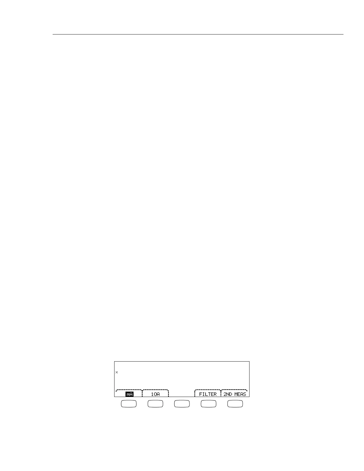
2. Press K.
0.0333
uA
~
F1 F2 F3 F4 F5
caw08f.eps

 Loading...


