7: Measuring I-V characteristics of FETs Model 2450 SourceMeter® Instrument
7-2 2450-900-01 Rev. E / August 2019
• The cabling for external hardware triggers depends on the command set you are using:
For SCPI commands, use a DB-9 male-to-male 9-pin cable to connect the digital I/O ports on
the back of the 2450 instruments to each other.
For TSP commands, you need a TSP-Link crossover cable (one RJ-45 LAN crossover cable
is included with your 2450) to connect the TSP-Link ports on the rear panel of the 2450
instruments to each other.
• Cabling from the computer to the 2450 instruments depends on the command set you are using:
For the SCPI command example, use two GPIB cables, two USB cables, or two ethernet
cables
For the TSP command example, use one GPIB cable, one USB cable, or one ethernet cable
Instructions for setting up the two 2450 instruments for this application are in the following
paragraphs.
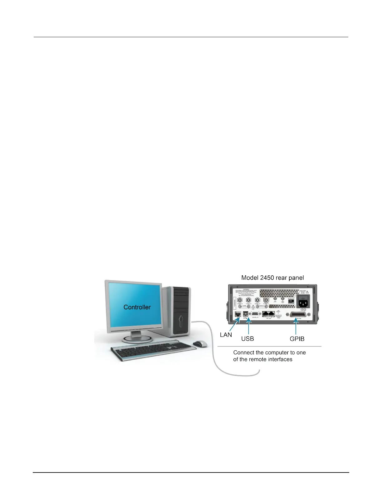
Set up remote communications
This application is configured to run remotely. You can run this application from any of the supported
communication interfaces for the instrument (GPIB, USB, or ethernet).
The following figure shows the rear-panel connection locations for the remote communication
interfaces.
Figure 35: 2450 remote interface connections
Set up external hardware triggers
To enable synchronization between the two 2450 instruments for stepping and sweeping voltages,
connect the external triggers of each instrument to the other. The cabling you use depends on which
2450 programming command set you choose to control the test.
 Loading...