7: Measuring I-V characteristics of FETs Model 2450 SourceMeter® Instrument
7-6 2450-900-01 Rev. E / August 2019
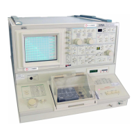
For this application, connect four triaxial cables (Model 7078-TRX-10) from the 2450 rear-panel
female triaxial connectors to the MOSFET device. Mount the MOSFET device in a metal-shielded test
fixture with female triaxial connectors. Connect the Force LO terminals of both 2450 instruments to
the Source terminal of the MOSFET using a triaxial tee connector (Model 237-TRX-T).
Remote control of FET testing using SCPI commands
The two example sequences of SCPI commands for this application generate a drain family of curves
on a FET using two 2450 instruments. One of the examples uses the trigger model to generate the
family of curves. The other example uses a linear sweep. You may need to make modifications for
operation in your programming environment.
Set up the application using SCPI commands with the trigger
model
In this application, the gate voltage steps from 2 V to 5 V in 1 V steps, the drain voltage sweeps from
0 V to 5 V in 51 steps, and the drain current is measured. The current and voltage measurements are
stored in defbuffer1. The 2450 trigger model synchronizes the two 2450 instruments.
You send commands to either the sweeper on the drain (SMU 1) or the stepper on the gate (SMU 2).
In the table, commands for the sweeper have a light gray background. Commands for the stepper
have a darker gray background. The light-brown shaded code represents pseudocode that will vary
depending on the programming environment you use. Each bulleted item in the Description column
describes a single line of code in the Commands column.
Send the following commands for this example application:
SMU 1,
SMU 2, or
pseudocode
Commands Description
:SENS:FUNC "CURR"
:SENS:CURR:RANG:AUTO ON
:ROUT:TERM REAR
:SOUR:FUNC VOLT
:SOUR:VOLT:RANG 20
:SOUR:CONF:LIST:CRE "stepVals"
:DIG:LINE1:MODE TRIG, OUT
:DIG:LINE2:MODE TRIG, IN
:TRIG:DIG1:OUT:STIM NOT1
:TRIG:DIG2:IN:CLE
:TRIG:DIG2:IN:EDGE RIS
Reset the instrument.
Set to measure current.
Set to measure with autorange
enabled.
Set to rear terminals.
Set to source voltage.
Set to 20 V source range.
Create a source configuration list
called stepVals.
Set digital line 1 to trigger out.
Set digital line 2 to trigger in.
Set the stimulus for digital line 1 to
the notify1 event.
Clear digital line 2.
Set to detect rising edge on line 2.
 Loading...