7: Measuring I-V characteristics of FETs Model 2450 SourceMeter® Instrument
7-10 2450-900-01 Rev. E / August 2019
SMU 1,
SMU 2, or
pseudocode
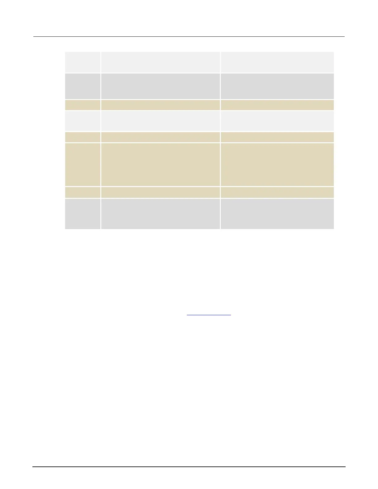
Commands Description
Set the source level to the iteration
number of the loop.
Delay for 500 ms to allow for settling.
SMU 2
*WAI
Trigger the sweep to start.
Wait for the operations to complete.
Pseudocode
Wait for sweep to complete.
for SMU 2
vds[i-1]=TRAC:DATA? 1, 51,
"defbuffer1", SOUR
ids[i-1]=TRAC:DATA? 1, 51,
"defbuffer1", READ
Receive each of 51 readings and
source values from the buffer and
save them in the arrays vds and ids,
respectively. The arrays start at index
one. Each point in the arrays contains
a list of values for each gate voltage.
End the
loop.
Turn the output off. NOTE: All of the
source and measure values can be
returned from the arrays vds and
.
Remote control of FET testing using TSP commands
The two example sequences of Test Script Processor (TSP
®
) commands for this application generate
a drain family of curves on a FET using two 2450 instruments. One of the examples uses the trigger
model to generate the family of curves. The other example uses a linear sweep. You may need to
make modifications for operation in your programming environment.
The following TSP code is designed to be run from Keithley Instruments Test Script Builder (TSB).
TSB is a software tool that is available from tek.com/keithley
. You can install and use TSB to write
code and develop scripts for TSP-enabled instruments. Information about how to use TSB is in the
online help for TSB and in the “Introduction to TSP operation” section of the Model 2450
Reference Manual.
To use other programming environments, you may need to make changes to the example TSP code.
By default, the 2450 uses the SCPI command set. You must select the TSP command set before
sending TSP commands to the instrument.
To enable TSP commands:
1. Press the MENU key.
2. Under System, select Settings.
3. Set the Command Set to TSP.
4. At the prompt to reboot, select Yes.