Maintenance
TDS 200 Series Digital Oscilloscope Service Manual
6–29
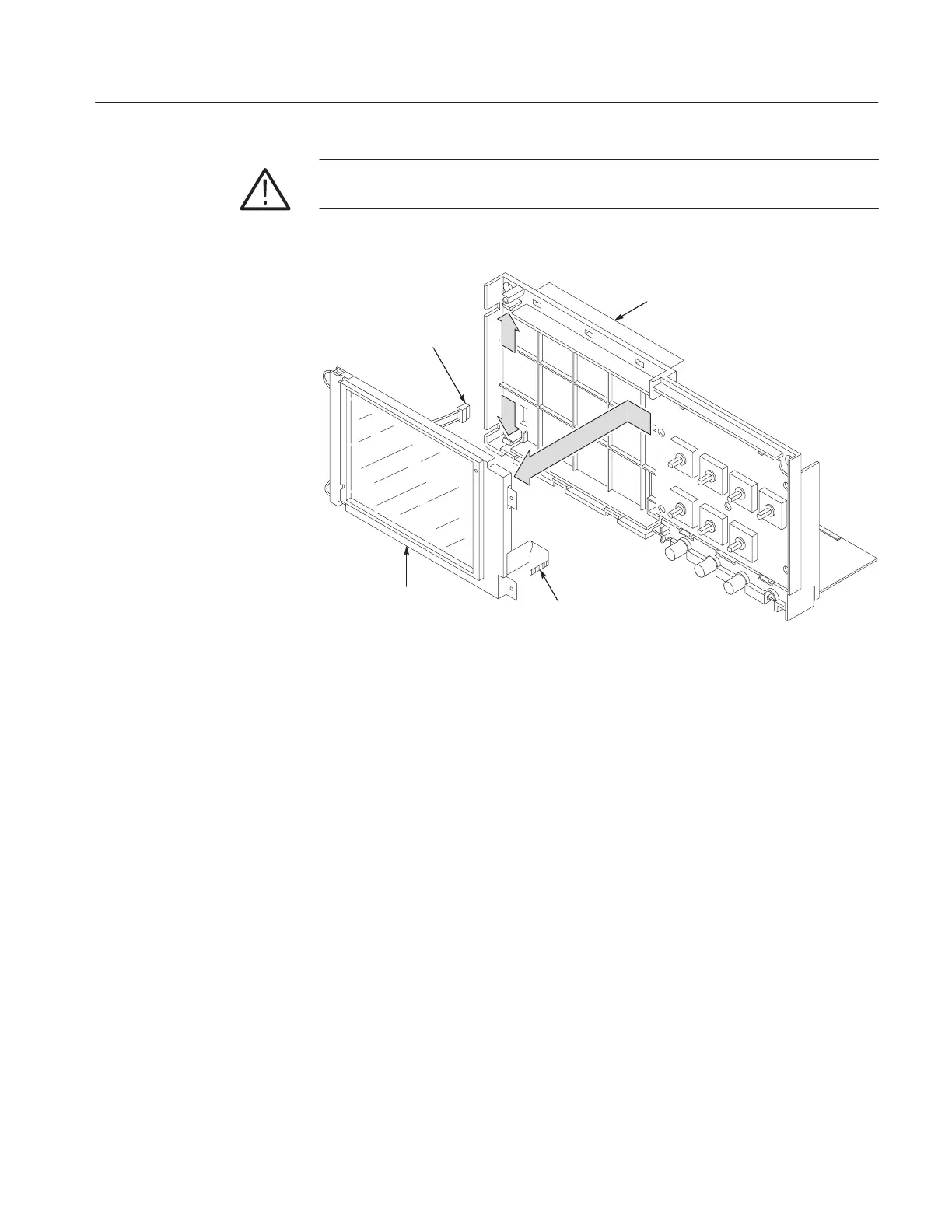
CAUTION. The display shield is attached to the display module. Removing the
shield will destroy the attaching gasket.
Internal chassis
Backlight
cable
Ribbon cable
Display module
Figure 6–19: Removing the display module
Installation. Use this procedure to install the display module.
1. Route the display ribbon cable through the opening in the internal chassis as
shown in Figure 6–20. If installing a new module, fold the ribbon cable as
shown.
2. Place the tabs on the right side of the display module into the slots of the
internal chassis located under the front panel board. It is not necessary to
remove the front panel board. Refer to Figure 6–20.
3. Route the backlight cable through the opening in the internal chassis as
shown in Figure 6–20.
4. Lower the left side of the display module into the internal chassis until the
two securing tabs lock on to the display module. Note that the backlight
cable protruding from each end of the module must align with the cutouts of
the inner chassis. Refer to Figure 6–20.
5. Reconnect the display module ribbon cable at J202 or J102 on the main
board by pushing the cable straight down into the connector. Refer to Figure
6–17.

 Loading...


