Maintenance
TDS 200 Series Digital Oscilloscope Service Manual
6–41
7. If all of the voltages are missing, check the line fuse on the power supply
module. If the fuse is defective, replace the fuse. If the fuse is ok, continue
with step 8.
8. If all or some of the voltages are missing, the power supply module is
probably defective. Replace it.
Follow these steps to troubleshoot a nonfunctional backlight.
1. Remove the rear case using the procedure Rear Case on page 6–14.
2. Turn the instrument on.
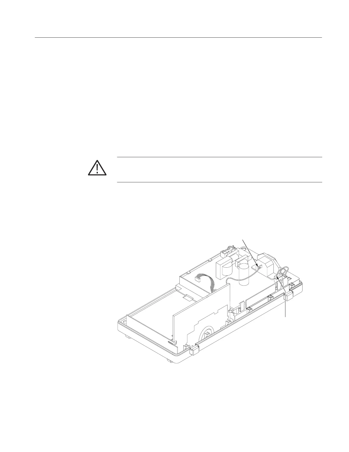
WARNING. To avoid electrical shock, do not touch the two-wire backlight
connector on the power supply module. The output connector is the one closest to
the power line cord.
3. Set the test oscilloscope (with a 100X probe) to measure a 1270 V
pk-pk
(450 V
RMS
) signal at approximately 60 kHz. Attach the probe ground lead to
the ground lug on the AC line connector and the probe tip to the backlight
connector as shown in Figure 6–26.
AC ground lug
Backlight voltage
test point
Figure 6–26: Measuring the backlight voltage
4. If the 1270 V
pk-pk
signal is present, the backlight is probably defective.
Replace the display. If the signal is not present proceed with step 5.
Backlight Troubleshooting

 Loading...


