INSTALLATION
100
NG10 - Manual - 04 - 2022
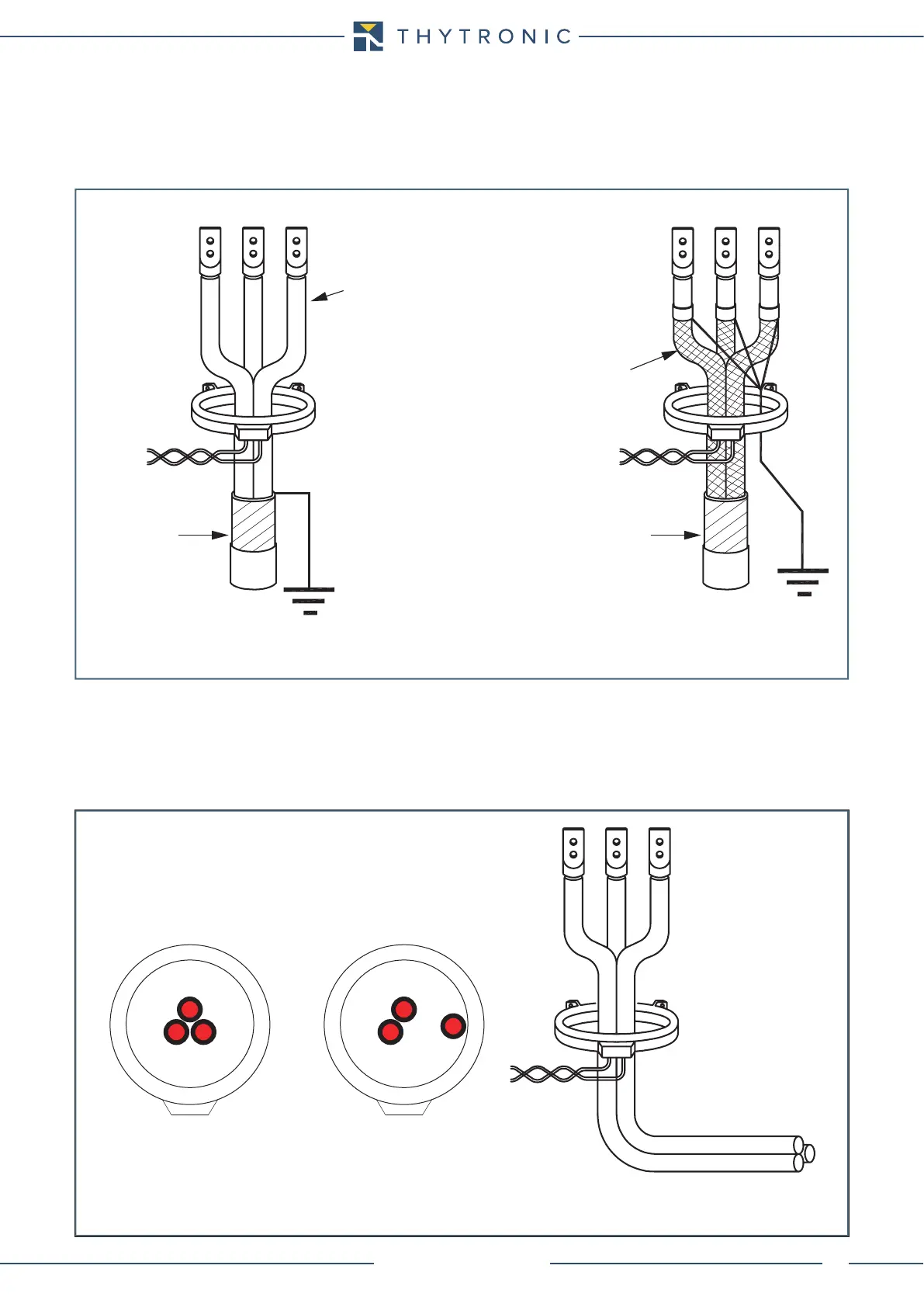
Core balanced CT
The current balance transformer, when used for measuring residual current, must be crossed in the
same direction by all active conductors and hence, also by the neutral conductor if distributed, with
the exception of the ground connection protective conductor. The drawing below shows cases of
assembly of the toroid on unscreened and screened cables; prior to proceeding with assembly, it is
necessary to check that there are no screen-to-ground connections upstream of the sensor.
In order to ensure a linear response from the sensor, the cables must be positioned in the centre
of the transformer so that the magnetic effect of the three cables is perfectly compensated in the
absence of residual current (Fig.2a).
Hence, the assembly indicated in the drawing of fig.2b, in which phase L3 causes local magnetic
saturation whereby the vectorial sum of the three currents would be non-null, should be avoided.
The same considerations also apply when the sensor is positioned near bends in the cabling.
It is recommended that the transformer be placed away from bends in the conductors (fig. 2c).
Fig. 1a
Fig. 1b
Armoring
Load Load
Source Source
Insulated cables
Shielded cables
Armoring
Toroide.ai
Current balanced transformer
L1
Fig. 2a Fig. 2b Fig. 2c
L3L2
L1
L3
L2
Toroide.ai
Current balanced transformer
 Loading...
