FUNCTION CHARACTERISTICS
41
NG10 - Manual - 04 - 2022
Communication interfaces
Several communication ports are provided:
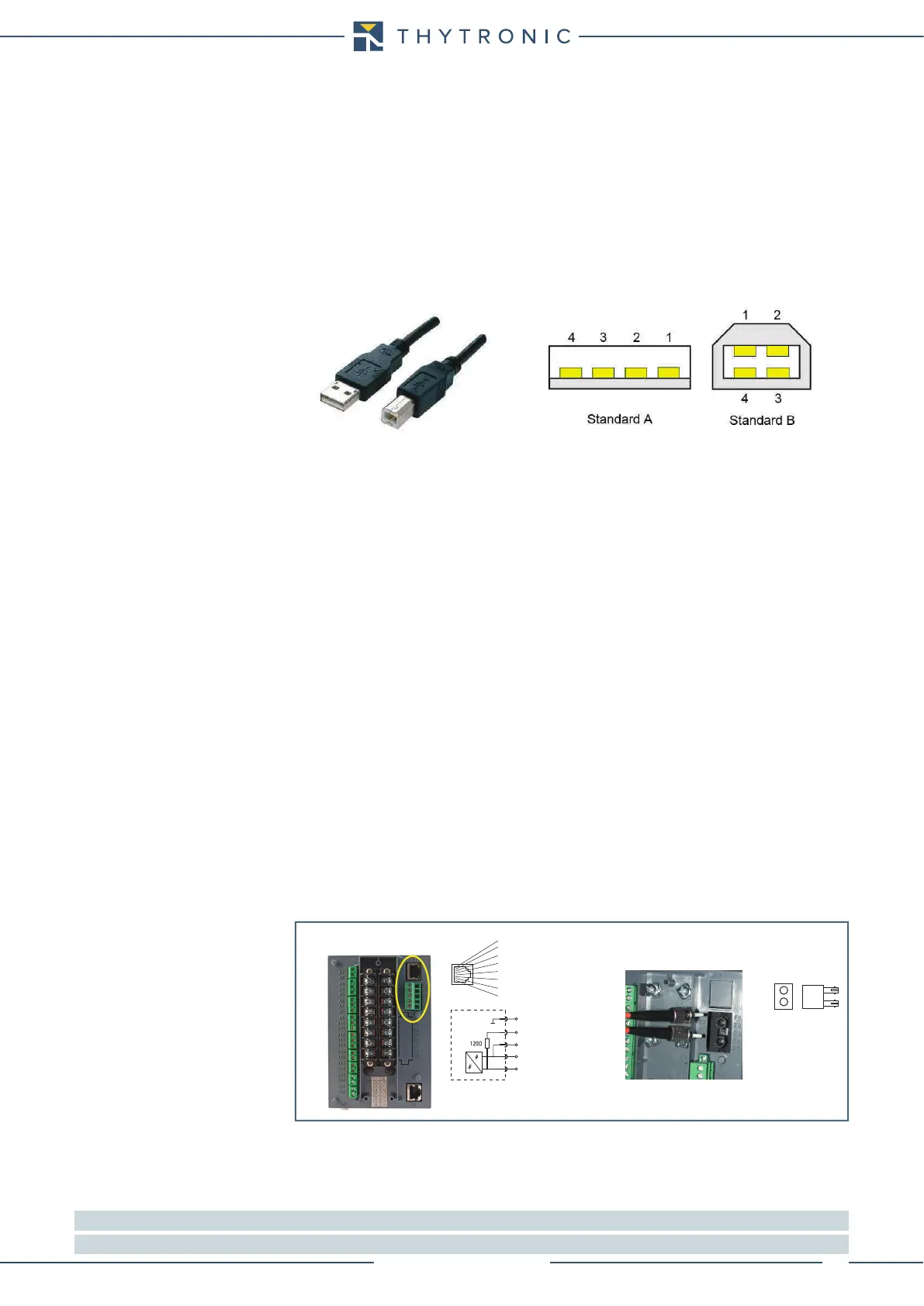
• USB port on the front side for local communication (ThyVisor).
• RS485 port on the rear side for bus communication.
• Ethernet port on the rear side for bus communication.
USB
To connect the local port you need to use a cable USB Type B - Type A; the Thytronic cable code
L10042 can be supplied.
The serial port is the simplest access for setting by means the ThyVisor software.
RS485
Several protocol are implemented
[1]
:
• ModBus RTU. Modbus is a serial communications protocol. It is a de facto standard communica-
tions protocol in industry, and is now the most commonly available means of connecting industrial
electronic devices also inside electric utilities and substation.
• IEC 60870-5. The IEC 60870-5 suite of protocol is used for communications from master station to
substation, as well within the substation; the IEC 60870-5-103 (Protection equipment) is available
together the Modbus protocol on some version of Pro-n devices (code Nxxx#xxxxC x).
Ethernet
It is provided (optionally) a communication board useful for Ethernet communication with ModBus
TCP/IP protocol.
[2]
Modbus/TCP basically embeds a Modbus frame into a TCP frame in a simple manner. This is a con-
nection-oriented transaction which means every query expects a response.
This query/response technique fits well with the master/slave nature of ModBus, adding to the de-
terministic advantage that Switched Ethernet offers industrial users.
In the same way as the RS485 base Modbus, every device is identified by a personal address and the
communication goes in “client-server” mode with answering request from the recipient.
The protective relay can be directly connect to the Ethernet network (no gateway, protocol converter
are needed).
Two port can be implemented:
• 100BASE-TX with RJ45 connector (copper).
• 100BASE-FX with FX connector (optical fiber)
[2]
For both modules no hw preset are required.
Two LEDs are on board (RJ45):
• LINK - (green): The LED lights up if the connection is active.
• TX - (yellow): The LED lights up when data transmission is active.
Note 1 The RS485 port is not implemented on the Pro-N devices endowed with Ethernet FX port
Note 2 Information about the ModBus map may be find inside the “Remote programming manual”
ethernet-sch.ai
RX
FX Ethernet (no RS485 port)
TX
1 TX+
2 TX-
3 RX+
4
5
6 RX-
7
8
RJ45 Ethernet+RS485 ports
RS485
F1
F2
F3
F4
F5
A+
B-
 Loading...
