FUNCTION CHARACTERISTICS
82
NG10 - Manual - 04 - 2022
CT supervision - 74CT - side H and side L
[1]
Preface
The CT monitoring function is employed to issue an alarm when secondary phase CTs and/or phase
input of the NT10 relay failure are detected. Interruptions are detected by means of a symmetry
criterion of the I
L1(H)
, I
L2(H)
, I
L3(H)
and
I
L1(L)
, I
L2(L)
, I
L3(L)
input currents.
The symmetry factor is calculated comparing the minimum and maximum of the fundamental compo-
nents of the three phase currents (I
LMIN(H)
/ I
LMAX(H)
for side H and I
LMIN(L)
/ I
LMAX(L)
for side L).
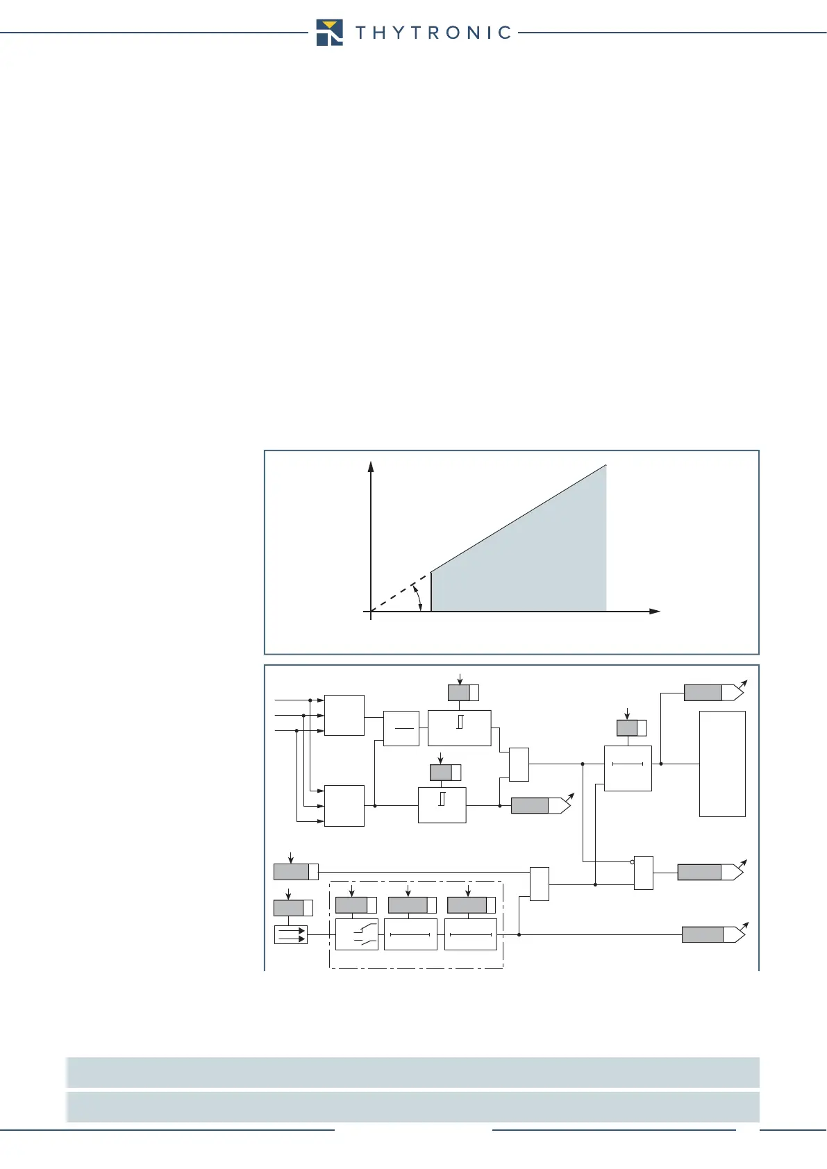
Operation and settings
The starting of the timer occurs if both the following conditions are filled:
A) I
LMIN(H)
/ I
LMAX(H)
) < S(H)<, that is the symmetry factor is lower than the S(H)<
adjustable thresh-
old for side H and I
LMIN(L)
/ I
LMAX(L)
) < S(L)<, that is the symmetry factor is lower than the S(L)<
adjustable threshold for side L;
B) I
LMAX(H)
> I(H)* for side H and/or I
LMAX(L)
> I(L)* for side L
Where
I(H)*, I(L)*: maximum phase current threshold
S(H)< S(L)<: element pickup value
t
S(H)
<, t
S(L)
<
:
operate time
After expiry of the associated operate time (t
S(H)
< for side H and t
S(L)
< for side L) a trip command is
issued; if instead the current drops below the threshold, the element it is restored.
The tripping characteristic is definite time.
The output may be assigned to the selected S(H)<TR-K output relays inside the Set \ CT supervision-
74CT- side H for side H and S(L)<TR-K output relays inside the Set \ CT supervision-74CT- side L for
side L menu; the same for addressing the LED indicators S(H)<TR-L and S(L)<TR-L.
The elements can be enabled or disabled by setting ON or OFF the 74CT(H)Enableparameter
inside the Set \ CT Supervision side H - 74CT side H menu for side H and 74CT(L)Enableparam-
eter inside the Set \ CT Supervision side L - 74CT side L menu for side L.
If the S(H)<-BLK1 and/or S(L)<-BLK1parameter is set to ON, and a binary input is designed for
logical block (Block1), the CT supervision function is blocked off whenever the given input is active.
The trip timer is held in reset condition, so the operate time counting starts when the input block
goes down.
[2]
All the parameters are common for A and B Profile
Note 1 The H index that identify the variables related to the H side are indicated inside the schematic diagrams; the operation of the protection of
thermal imaging side L is similar to that of the side H.
Note 2 The exhaustive treatment of the logic block (Block 1) function may be found in the “Logic Block” paragraph inside CONTROL AND MONITORING
section
char74CT.ai
I
(H)
*
α
I
LMIN(H)
I
LMAX(H)
tgα=S
(H)
<
Current asimmetry monitoring - 74CT - side H
TRIP
NO TRIP
CT monitoring logic diagram - 74CT
Fun-74CT.ai
&
0
T
t
s
<
t
S<
I
LMIN
/I
LMAX
<
S<
S<
TRIPPING MATRIX
(LED+RELAYS)
Trip S<
Start I*
BLK1 S<
I
LMAX
>I*
I*
Enable (ON≡ Enable)
Block1 input (ON≡ Block)
&
&
S<BLK1
Block1
Block1
Binary input INx
T 0
Logic
INx
t
ON
INx
t
ON
INx
t
OFF
T0
n.o.
n.c.
INx
t
OFF
I
L1
I
LMAX
I
L2
I
L3
I
LMIN
I
LMIN
I
LMAX
S<TR-K
S<TR-L
RESET
 Loading...
