FUNCTION CHARACTERISTICS
56
NG10 - Manual - 04 - 2022
Low impedance restricted ground fault- 64REF
Preface
One operation threshold with adjustable intentional delay with definite time characteristic.
Operation and settings
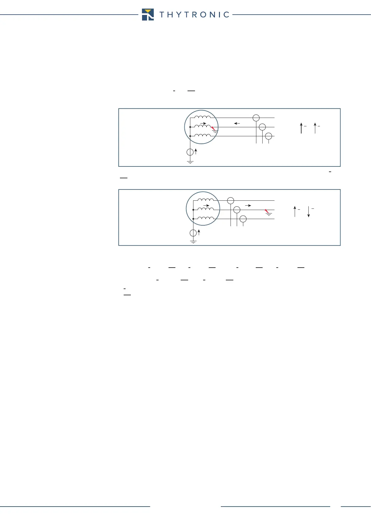
When there is no earth fault, no starpoint current I
E
flows and the computed residual current
(I
E(H)
= I
L1(H)
+ I
L2(H)
+ I
L3(H)
) is also zero.
i
E
and i
E(H)
are conventionally regarded as positive if coming into their respective amperometric
clamp reference input (C7 per i
E1
, C1-C3-C5 per i
E(H)
), negative if outgoing.
For internal fault to the protected area (I
L2(H)
in the following example), i
E
and i
E(H)
are thus both
positive, ie the phasors I
E
and I
E(H)
are in phase (assuming the same system of grounding of the star
point and network).
When the fault is outside the protected area i
E
is positive and i
E(H)
is negative ie phasors I
E
and
I
E(H)
are opposite in phase.
The residual fundamental frequency current, acquired by means of a current transformer installed in
the starpoint connection to ground - side H, is compared with the stabilization current defined as:
I
ES(H)
= 4 · [|p
E
·I
E
- ME
(H)
·I
E(H)
| - |p
E
·I
E
+ ME
(H)
·I
E(H)
|] se [|p
E
·I
E
- ME
(H)
·I
E(H)
| - |pE·I
E
+ ME
(H)
·I
E(H)
|] > 0
or
I
ES(H)
= 0 if [|p
E
·I
E
- ME
(H)
· I
E(H)
| - |p
E
·I
E
+ ME
(H)
·I
E(H)
|] ≤ 0, where:
• I
E
is the residual current phasor,
• I
E(H)
is the calculated residual current (fundamental wave of the phase currents sum) side H,
• p
E
is the amperometric polarity of the residual current so that it can be corrected any possible re-
versal of polarity; if the amperometric polarity is according the schematic connection diagram the
corresponding setting is C7-C8POL=NORMAL(pE1 = +1), otherwise is INVERSE (pE1 = -1).
The C7-C8POLparameter is available inside the Set \ Polarity menu.
• ME
(H)
is an amplitude compensating factor of residual current calculated by the relay as follows
from the I
np
, I
n
, I
Enp
,
I
En
, parameters setting inside the Set \ Base menu:
ME
(H)
= (I
np(H)
/ I
n(H)
) / (I
Enp
/ I
En
)
The ME
(H)
factor expresses the value that is multiplied by the residual current calculated by the cur-
rent of phase CTs in order to obtain an amplitude equal to that of the residual current measured by
CT on grounding the neutral in case of earth fault outside the protected area. The relay also checks
that the ME
(H)
value is ≤ 200 and if this condition is not met, the relay displays a warning and requires
the programming of parameters I
np(H)
, I
n(H)
, I
Enp
, I
En
available inside the Set \ Base menu. Being com-
pensated in amplitude the calculated residual current, the threshold setting of the element is always
referred to the rated current of the CT on grounding connection of neutral (I
E
).
The current i
E
and i
E(H)
are conventionally regarded as positive if entrants in their respective ref-
erence terminal of the current input, whether negative terminals. Internal fault in the protected
area, i
E
and i
E(H)
are thus both positive, and that the phasors are in phase (assuming the same sys-
tem of earthing of the star and the network), while a fault outside the protected area i
E
is positive
and i
E(H)
negative and that the phasors are in phase opposition.
To understand how the 64REF element does work, to simplify, consider PE1 = +1 and ME(H)=1, , accord-
ing to the connection diagram and use of CTs with the same ratio on the grounding neutral-side H.
The trip current is the residual current measured directly by the CT on the starpoint grounding con-
nection.
The stabilization current is computed by the relay using the sum and difference method of the cur-
rents on the grounding path (direct measurement) and line currents (calculated as sum of phase
currents). The current stabilization thus depends on the residual current values as well on the their
displacement angle .
I
E
I
E
I
E(H)
= i
L1(H)
+ i
L2(H)
+ i
L3(H)
L1
L2
L3
I
L2(H)
I
E
I
E(H)
I
L2
(H)
I
E
I
E
L1
L2
L3
I
E
I
E(H)
= i
L1(H)
+ i
L2(H)
+ i
L3(H)
I
E(H)
 Loading...
