Adjusting the Lift-Arm Turnaround Position
1. Park the machine on a level surface, lower the cutting units, shut off the engine, engage
the parking brake, and remove the key.
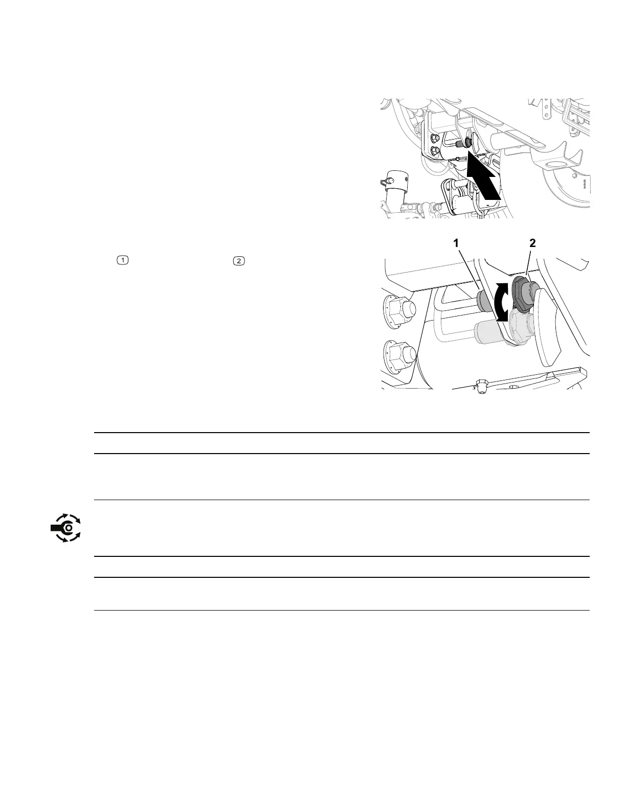
G439043
2. Locate the lift-arm switch underneath the
hydraulic tank and inboard of the cutting unit
#5 lift arm.
G439054
3. Loosen the jam nut that secures lift-arm switch
to the switch plate .
4. Adjust the lift-arm switch as follows:
• To increase the lift-arm turnaround height,
move the switch down.
• To decrease the lift-arm turnaround height,
move the switch up.
IMPORTANT
Maintain an air gap of 1.0 to 2.5 mm (0.040 to 0.100 inches) between the switch and
the lift-arm trigger. The LED light on the switch verifies proper function of the switch.
5. Torque the jam nuts to 20 +/- 2 N∙m (15 +/- 1.5 ft-lb).
IMPORTANT
Do not overtorque the jam nuts; otherwise, you may damage the sensor.
3464-482A Page 5–29 Operation: During Operation

 Loading...

