CHASSIS
2 - 20 260 Series Tractor Service Manual
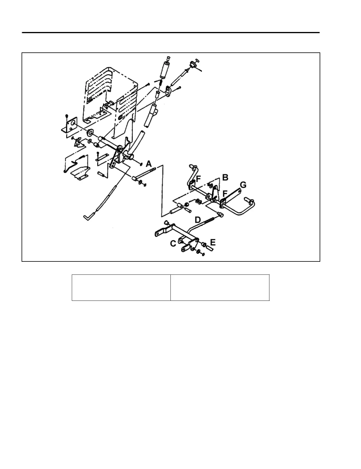
Lift Arm Linkage
Figure 59 7-3
The lift arm linkage is responsible for raising and
lowering the attachment and is made up of the
following main components:
•Lift rod
• Rear lift arm assembly
• Front lift arm assembly
• Leveling rod
• Cross shaft
• Gauge wheel lift link
• Mounting brackets
The lift rod, A, is connected to the lift lever weldment
and the rear lift arm assembly, B. The rear lift arm
assembly is attached to the front lift arm assembly, C,
by a leveling rod, D. It is also bolted to rear frame
hangers at the mounting brackets, F.
The front lift arm assembly, C, is secured to the tractor
by a cross shaft, E, which is mounted to the bottom of
the footrests. The mower gauge wheel lift link is
connected to the rear lift arm assembly at point G.
When the lift lever is moved, the lift rod, A, rotates the
rear lift arms, B, through the mounting brackets, F. The
gauge wheel lift link (connected to the rear lift arm
assembly at point G) raises and lowers with the lift
arms.
The front lift arms, C, rotate on the cross shaft, E.
Because the front lift arms are connected to the rear lift
arm assembly by a leveling rod, D. They also raise
and lower with the rear lift arms.
(A) Rod
(B) Rear Lift Arm Assembly
(C) Front Lift Arm Assembly
(D) Leveling Rod
(E) Cross Shaft
(F) Mounting Brackets
 Loading...