ELECTRICAL SYSTEMS
6 - 2 260 Series Tractor Service Manual
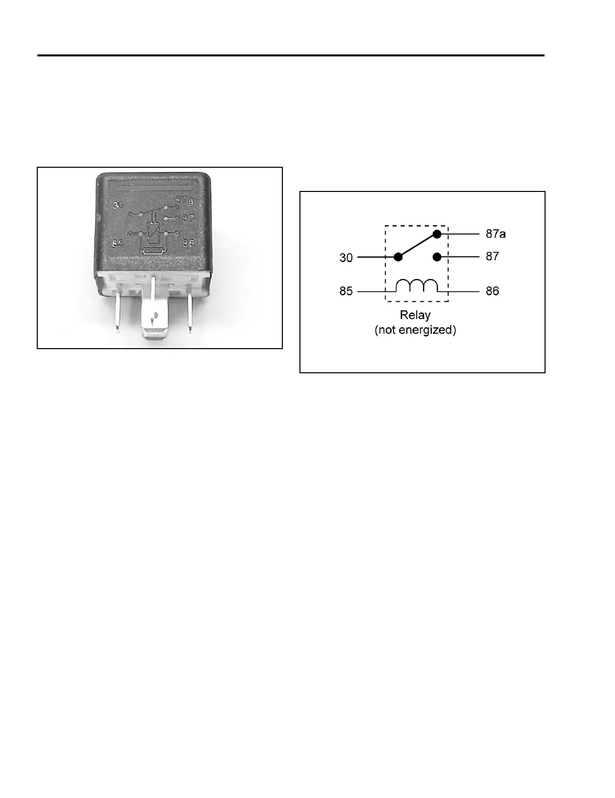
2. Switch: Terminals 30, 87, and 87a are actually
part of a single pole, double throw (SPDT) switch.
Terminal 30 is the common lead. The switch is
spring loaded so that 30 and 87a are connected
when the coil is not energized. When the coil is
energized, the switch is “thrown” and 30 and 87
are connected (Figure 219).
Figure 219
MVC-671X
Testing
1. Disconnect the relay from the harness.
2. Verify the coil resistance between terminals 85
and 86 with a multimeter (ohms setting).
Resistance should be from 70 to 90 ohms. There
should be continuity between terminals 87a and
30.
3. Connect multimeter (ohms setting) leads to relay
terminals 30 and 87. Ground terminal 86 and
apply +12 VDC to terminal 85. The relay should
make and break continuity between terminals 30
and 87 as 12 VDC is applied and removed from
terminal 85.
4. Connect multimeter (ohms setting) leads to relay
terminals 30 and 87a. Apply +12 VDC to terminal
85. With terminal 86 still grounded, the relay
should break and make continuity between
terminals 30 and 87a as 12 VDC is applied and
removed from terminal.
5. Disconnect voltage and multimeter leads from
relay terminals.
Figure 220
XL Relay
Solenoid
Purpose
The solenoid’s purpose is simply to connect the battery
to the starter motor when the ignition switch is turned to
“START”. The solenoid is used to protect the ignition
switch from the high current drawn by the starter motor.
 Loading...