InstallingHydraulicHosesandTubes(O-RingFaceSeal)
g212099
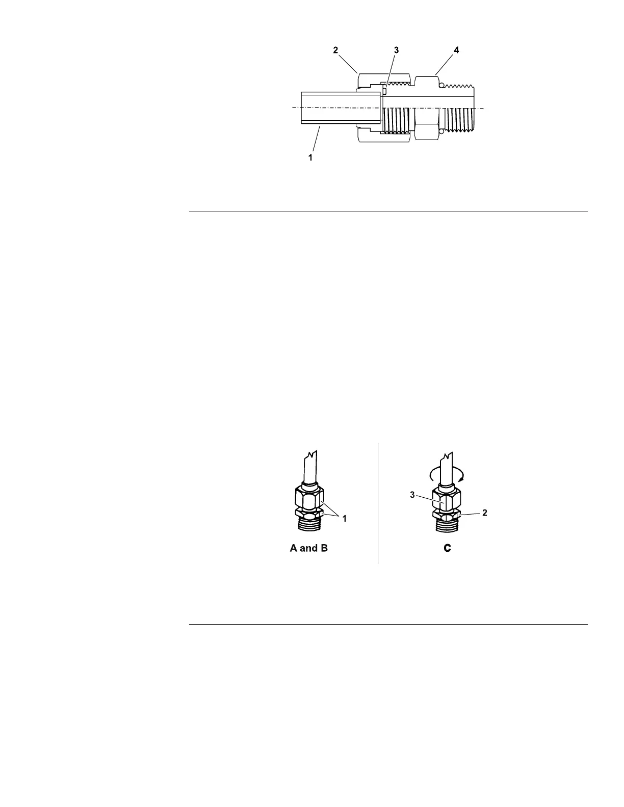
Figure22
1.Tubeorhose
2.Swivelnut3.O-ring
4.Fittingbody
1.Ensurethatallthethreads,thesealingsurfacesofthehose/tube,andthe
ttingarefreeofburrs,nicks,scratches,orunwantedmaterial.
2.Tohelppreventahydraulicleak,replacethefacesealO-ringwhenyouopen
theconnection.EnsurethattheO-ringisinstalledandcorrectlyseatedinthe
grooveofthetting.LightlylubricatetheO-ringwithcleanhydraulicuid.
3.Alignthehose/tubeagainstthebodyofthettingsothattheatfaceofthe
hose/tubesleevefullytouchestheO-ringinthetting(Figure22).
4.Useyourhandtothreadtheswivelnutontothetting.Whileyouholdthe
hose/tubeinalignmentwithawrench,useatorquewrenchtotightenthe
swivelnuttotherecommendedtorquevaluewithinthespeciedrangeof
torquevalues;refertotheHose/TubeInstallationT orqueTable(page4–4).
Thisproceduretotightentheswivelnutrequiresadrive-adapterwrench
(e.g.,crowfootwrench).
Note:Itmaybenecessarytouseadrive-adapterwrench(e.g.,crowfoot
wrench)toinstallahydraulictting;refertoCalculatingtheT orqueValues
WhenUsingaDrive-AdapterWrench(page2–5).
g212098
Figure23
1.Markswivelnutandtting
body
2.Initialposition3.Finalposition
Groundsmaster®1200Pull-BehindRotaryMower
Page4–3
HydraulicSystem:GeneralInformation
18235SLRevA
 Loading...