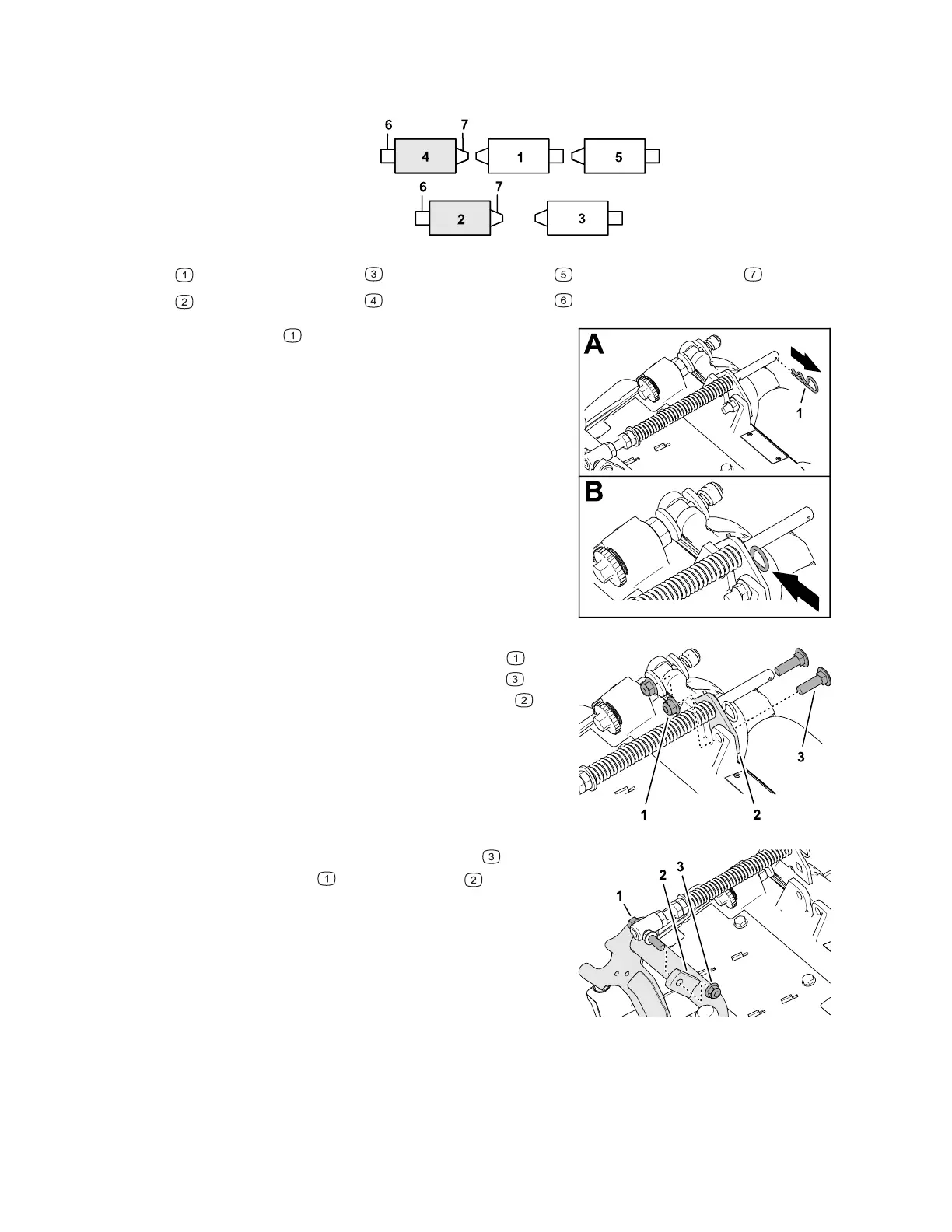
Positioning the Turf-Compensation Spring
Cutting Units 2 and 4
G402717
Cutting unit 1
Cutting unit 2
Cutting unit 3
Cutting unit 4
Cutting unit 5
Reel motor
Weight
G402718
1. If the hairpin is installed in the rear hole of
the compensation-spring rod, remove the
hairpin and insert it in the hole next to the
bracket.
G402719
2. Remove the 2 flange locknuts (3/8 inch)
and 2 carriage bolts (3/8 x 1-1/4 inches)
that secure the turf-compensator bracket to
the cutting-unit frame.
G402720
3. Remove the flange locknut (3/8 inch)
securing the bolt to the right tab of the
carrier frame, and remove the compensation
spring from the cutting unit.
Note: Do not remove the flange serrated nut
from the bolt.
3464-478A Page 3–4 Setup: Installing the Cutting Units
 Loading...