INTERFACE MANUAL
8.1.2 Connecting Extension Output Signal Cable
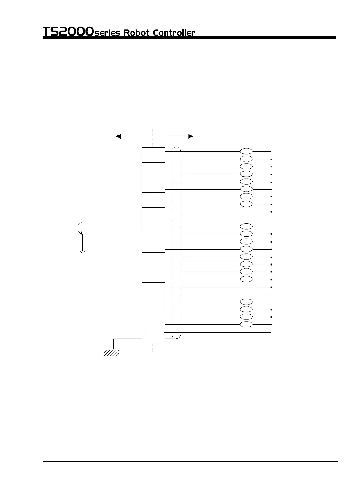
To connect the extension output signal cable, use the connector attached to the
TR48DIOCN module [XM2A–2501 (plug type connector), XM2S–2511 (connector
cover)]. Connect the outputs of the TR48DIOCN (DO_101 ~ 120 (station 0) and
DO_133 ~ 152 (station 1) to connector OUTPUT provided on the module surface.
OUTPUT
TR48DIOCN User side
1
14
2
15
3
16
4
17
5
18
6
19
7
20
8
21
9
22
10
23
11
24
12
25
13
Case
P24V
P24V
P24V
P24V
P24V
Station 0/Station 1
~
P24G
Sink type ("-" common)
DO_10 DO_120
~DO_133 DO_152
Note 1:
All of DO_101 ~ 120, DO_133 ~
152 in the figure above are the
transistor outputs.
DO_101/DO_133
DO_102/DO_134
DO_103/DO_135
DO_104/DO_136
DO_105/DO_137
DO_106/DO_138
DO_107/DO_139
DO_108/DO_140
DO_109/DO_141
DO_110/DO_142
DO_111/DO_143
DO_112/DO_144
DO_113/DO_145
DO_114/DO_146
DO_115/DO_147
DO_116/DO_148
DO_117/DO_149
DO_118/DO_150
DO_119/DO_151
DO_120/DO_152
(Station 0/Station 1):
Signal name of DOUT command
(101/133)
(102/134)
(103/135)
(104/136)
(105/137)
(106/138)
(107/139)
(108/140)
(117/149)
(118/150)
(119/151)
(120/152)
(109/141)
(110/142)
(111/143)
(112/144)
(113/145)
(114/146)
(115/147)
(116/148)
FG
The specifications of the extension output signal are the same as those of the
digital output signal (i.e., sink type) which are described in Para. 4.7.
STE 71367
– 101 –

 Loading...