INTERFACE MANUAL
4.4 Digital Input Signal
Designation Digital input signal
DI_1 ~ DI_32, DI_33 ~ DI_38 (system input signals)
Connector input
terminal
Signals DI_1 ~ DI_24 are assigned to CN5–1 ~ 12 pins and 20
~ 31 pins. (See Fig. 4.1 and 4.2.)
DI_24 can be used as signal ALM_RST by changing the user
parameter.
DI_25 ~ DI_32 are assigned to CN12–1 ~ 4 pins and 14 ~ 17
pins. (See Fig. 4.5 and 4.6.)
The system input signals assigned to CN5–13 ~ 15 pins and
32 ~ 34 pins can be used as signals DI_33 ~ DI_38 by
changing the user parameter.
Function Each signal status of DI_1 ~ DI_38 can be identified by the
robot program (DIN command) to branch the processing of
program. Also, it is possible to perform interruptive
processing of each signal (DI_1 ~ DI_38) with change in signal
status monitored during the robot operation.
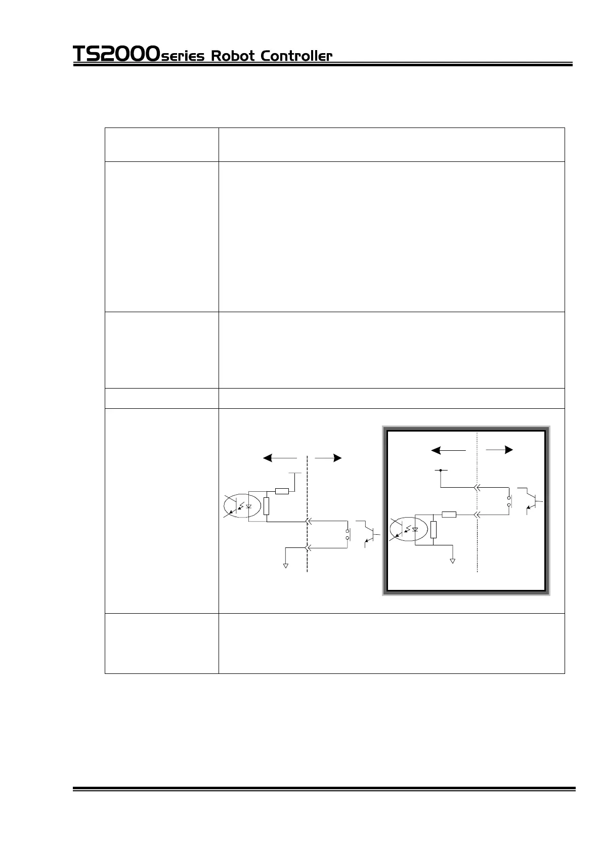
Input type Non-voltage contact input or transistor open collector input.
Example of circuit
(Input circuit
structure)
●
●
P24V
●
[ Source type ("+" common) ]
TS2000/TS2100 User side
P24G
Contact or
transistor
●
●
P24G
P24V
Contact or
transistor
User sideTS2000/TS2100
[ Sink type ( " -" common) ]
Signal logic Input terminal Signal judgment
Open OFF
Short-circuit ON
STE 71367
– 36 –

 Loading...