DIAGNOSIS
- Diagnostic Code
s
DIAGNOSTIC CODE
S
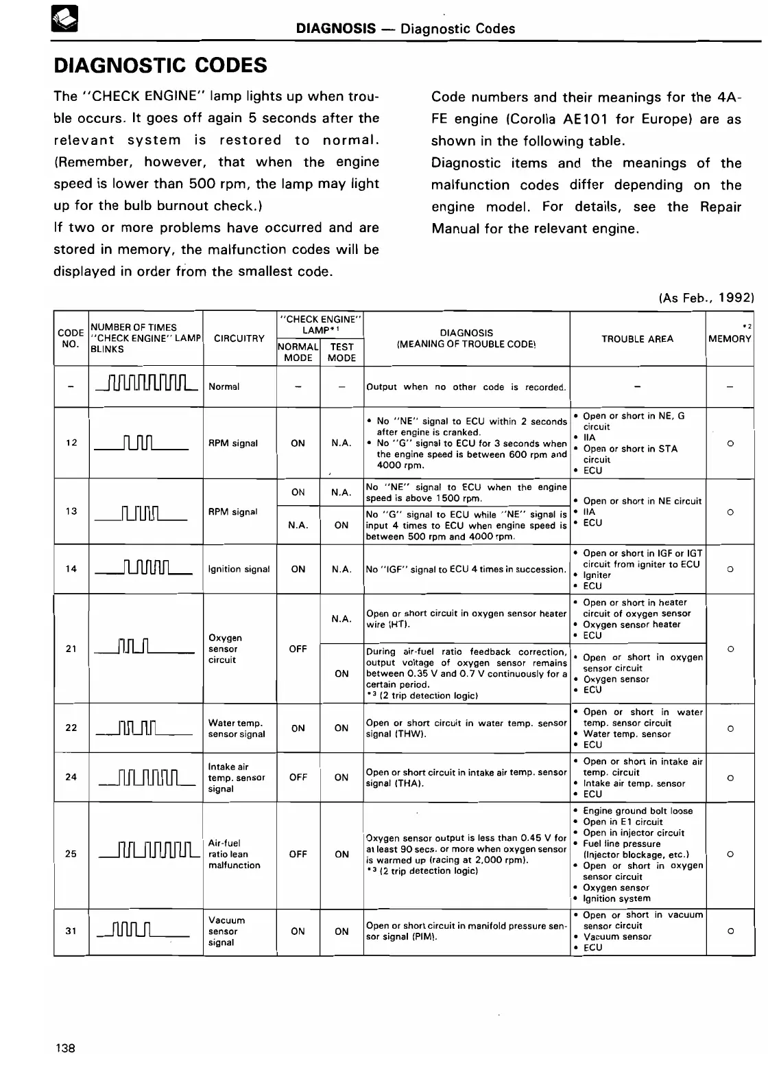
The "CHECK ENGINE" lamp lights up when trou-
ble occurs
. It goes off again 5 seconds after the
relevant system is restored to normal
.
(Remember, however, that when the engine
speed is lower than 500 rpm, the lamp may light
up for the bulb burnout check
.
)
If two or more problems have occurred and are
stored in memory, the malfunction codes will be
displayed in order from the smallest code
.
Code numbers and their meanings for the 4A-
FE engine (Corolla AE101 for Europe) are as
shown in the following table
.
Diagnostic items and the meanings of the
malfunction codes differ depending on the
engine model
. For details, see the Repair
Manual for the relevant engine
.
(As Feb
., 1992
)
C
E
NGINE
"
"C
H
CODE
NUMBER OF TIME
S
"CHECK ENGINE"
LAMP
CIRCUITRY
L
A~
P
DIAGNOSIS
2
NO
.
BLINKS
NORMAL
TEST
(MEANING OF TROUBLE CODE)
TROUBLE AREA
MEMOR
Y
MODE
MOD
E
-
J Ll LI LI LI LJ LI LI L
Normal
- -
Output when no other code is recorded
.
-
-
• No "NE" signal to ECU within 2 seconds
• Open or short in NE,
G
after engine is cranked
.
circui
t
12
RPM signal
ON
N
.A
.
• No "G" signal to ECU for 3 seconds when
• IIA
0
the engine speed is between 600 rpm and
• Open or short in ST
A
4000 rpm
.
circui
t
• EC
U
ON
N
.A
.
No "NE" signal to ECU when the engin
e
speed is above 1 500 rpm
.
• Open or short in NE circui
t
13
n n n n
RPM signal
No "G" signal to ECU while "NE" signal is
• IIA
0
N
.A
.
ON
input 4 times to ECU when engine speed is
• EC
U
between 500 rpm and 4000 rpm
.
• Open or short in IGF or IG
T
14
n UJ
j
L_
Ignition signal
ON
N
.A
.
No
"
IGF" signal to ECU 4 times in succession
.
circuit from igniter to ECU
O
• Ignite
r
• EC
U
• Open or sho
rt
in heate
r
N
.A
.
Open or sho
rt
circuit in oxygen sensor heater
circuit of oxygen senso
r
wire
(HT)
.
• Oxygen sensor heate
r
rI
Oxygen
• EC
U
21
n n
sensor
OFF
During air-fuel ratio feedback correction,
O
circuit
output voltage of oxygen sensor remains
• Open or short in oxyge
n
ON
between 0
.35 V and 0
.7 V continuously for a
sensor circui
t
ce
rt
ain period
.
• Oxygen senso
r
" (2 trip detection
logic)
• EC
U
• Open or short in wate
r
22
n n n n
Water temp
.
ON
ON
Open or sho
rt
circuit in water temp
. sensor
temp
. sensor circui
t
sensor signal
signallTHWI
.
•
Water temp
. sensor
0
• ECU
Intake air
• Open or sho
rt
in intake ai
r
24
temp
. sensor
OFF
ON
Open or short
circuit in intake air temp
. sensor
temp
. circuit
0
signal
signal
(
THA)
.
• Intake air temp
. senso
r
• ECU
• Engine ground bolt loos
e
• Open in E1 circui
t
Oxygen sensor output is less than 0
.45 V for
• Open in injector circui
t
25
J U LJ I
.J IJ
U LJ L
Air-fue
l
ratio lean
OFF
ON
at least 90 secs
. or more when oxygen sensor
• Fuel line pressur
e
(Injector
blockage, etc
.)
0
malfunction
is warmed up
(racing
at 2,000
rpm)
.
3
*3 (2
trip detection
logic)
• Open or sho
rt
in oxyge
n
sensor circui
t
• Oxygen senso
r
• Ignition syste
m
Vacuum
• Open or short in vacuu
m
31
n n n n
sensor
ON
ON
Open or short circuit in manifold pressure sen- sensor circuit
O
signal
sor signal
(
PIM)
.
• Vacuum senso
r
• EC
U
138
 Loading...