ELECTRONIC CONTROL SYSTEM
- Vehicle Speed Senso
r
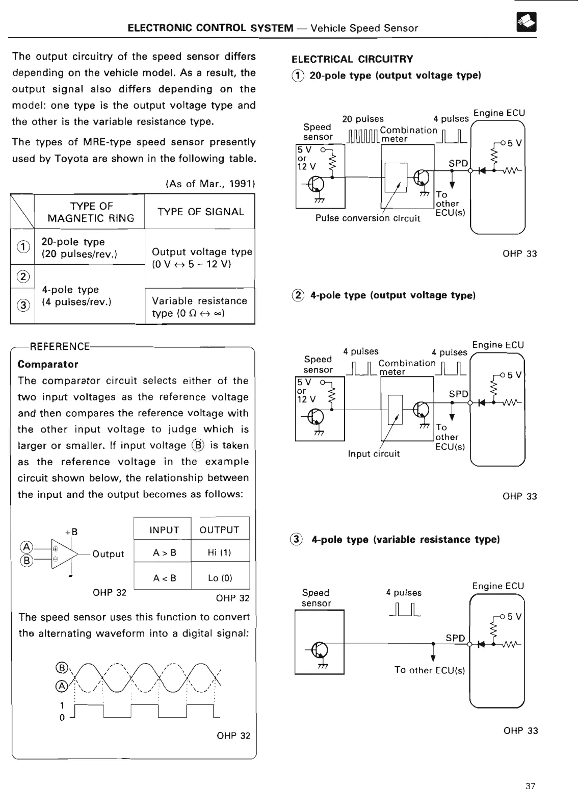
The output circuitry of the speed sensor differs
depending on the vehicle model
. As a result, the
output signal also differs depending on the
model
: one type is the output voltage type and
the other is the variable resistance type
.
The types of
MRE-type
speed sensor presently
used by Toyota
are shown in the following table
.
(As of Mar
., 1991
)
TYPE OF
TYPE OF SIGNA
L
MAGNETIC RIN
G
C
20-pole typ
e
(20 pulses/rev
.)
Output voltage typ
e
5-12V
)
(0V
H
4-pole typ
e
30,
(4 pulses/rev
.)
Variable resistanc
e
type
(0 12 H
-
)
REFERENCE
Comparator
The comparator circuit selects either of the
two input voltages as the reference voltage
and then compares the reference voltage with
the other input voltage to judge which is
larger or smaller
. If input voltage 'B` is taken
as the reference voltage in the example
circuit shown below, the relationship between
the input and the output becomes as follows
:
Outpu
t
OHP 32
INPUT
OUTPU
T
A> B
Hi (1
)
A < B
Lo (0
)
OHP 3
2
The speed sensor uses this function to convert
the alternating waveform into a digital signal
:
1
OHP 32
ELECTRICAL CIRCUITR
Y
-11-`
20-pole type
(
output voltage type)
®
20 pulses 4 pulses Engine EC
U
Speed Combination
n
sensor
111111111111
mete
r
4-pole type (output voltage type
)
4 pulses 4 pulse
s
Speed Combinatio
n
sensor
-1 LJ
L mete
r
Input circui
t
C 4-pole type (
variable resistance type)
OHP 3
3
Engine EC
U
OHP 3
3
OHP 3
3
37
 Loading...