INSPECTION AND ADJUSTMENT
- Feedback Correctio
n
FEEDBACK
CORRECTIO
N
OBJECTIVE
:
To learn how to check feedback correction
.
PREPARATIONS
:
• SST 09843-18020 Diagnosis check wir
e
• Analog type voltmeter
(
also called "circuit tester" or "multi-tester")
APPLICABLE ENGINE
: 4A-FE (
Sep
., 1989
)
MODELS
W/OXYGEN
SENSOR (02 SENSOR)
CHECKING FEEDBACK CORRECTIO
N
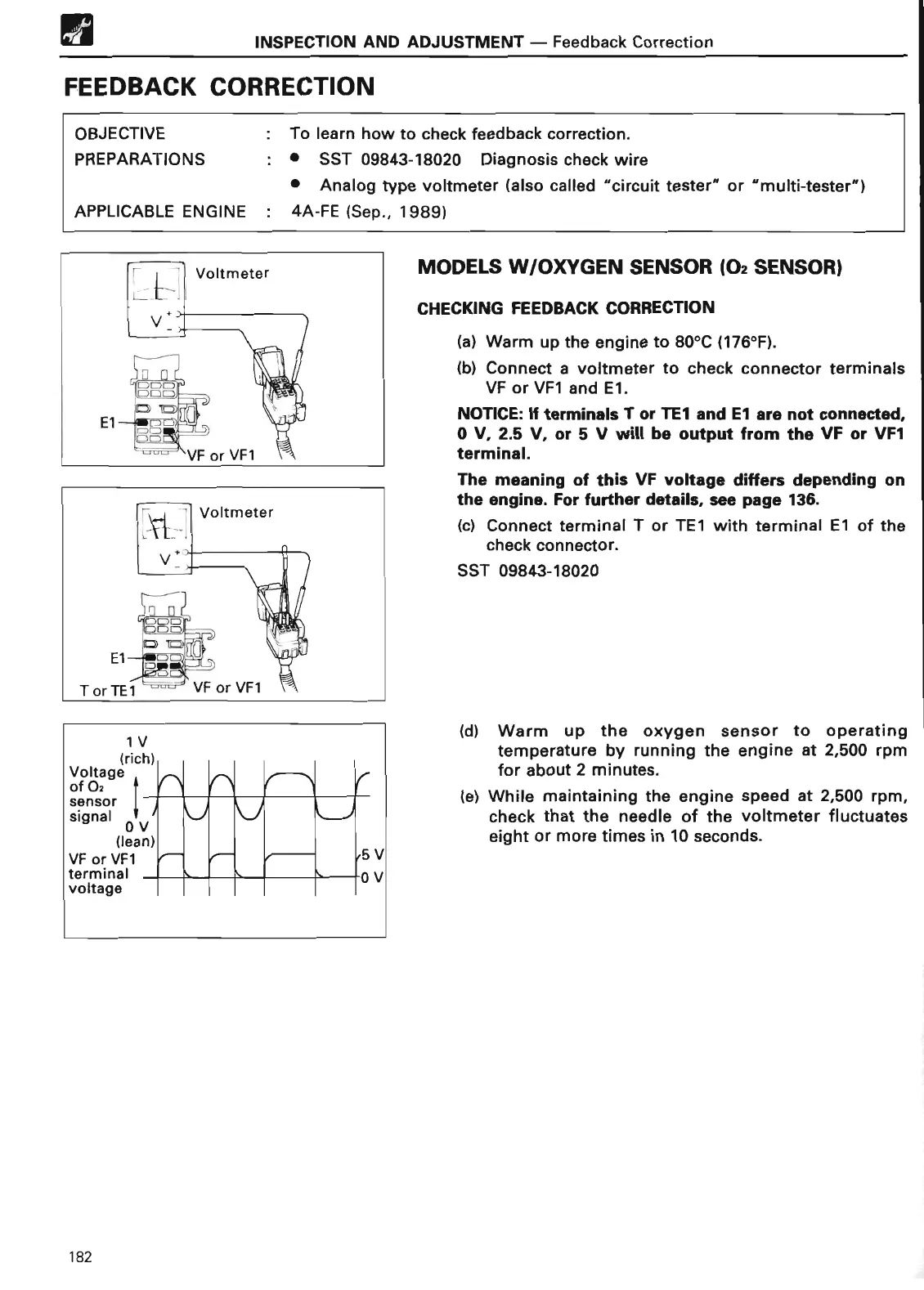
(a) Warm up the engine to 80°C (176°F)
.
(b) Connect a voltmeter to check connector terminals
VF or VF1 and E1
.
NOTICE
: If
terminals T or TE7 and E7 are not connected,
0 V, 2
.5 V, or 5 V will
be output from
the VF or VF1
terminal
.
The meaning
of this VF
voltage differs depending on
the engine
. For fu
rt
her details, see page 136
.
(c) Connect terminal T or TE1 with terminal El of the
check connector
.
SST 09843-1802
0
(d) Warm up the oxygen sensor to operating
temperature by running the engine at 2,500 rpm
for about 2 minutes
.
(e) While maintaining the engine speed at 2,500 rpm,
check that the needle of the voltmeter fluctuates
eight or more times in 10 seconds
.
182
 Loading...